Analyzing pin read exercise disassembly with O0 and O2
In the previous article, when we activated the O2 optimization on our code, our code stopped working. We have to investigate why it is not working.
Because, this investigation is very much required to understand how volatile works, and this will help us in understanding the volatile type qualifier in the next article.
Let’s investigate the disassembly code. First, let me activate the O0 optimization.
O0 optimization
Here, the main logic of our code is, if the pin status is 1, then LED will be turned on and if the pin status is 0, LED will be turned off. That means processors should read (uint8_t)(*pPortAInReg & 0X1) this memory location again and again and it has to update variable pinStatus.
So, for every loop, the processor reads the memory location, and then it updates the variable, and based on that decision will be taken.
Let’s analyze what’s happening here.
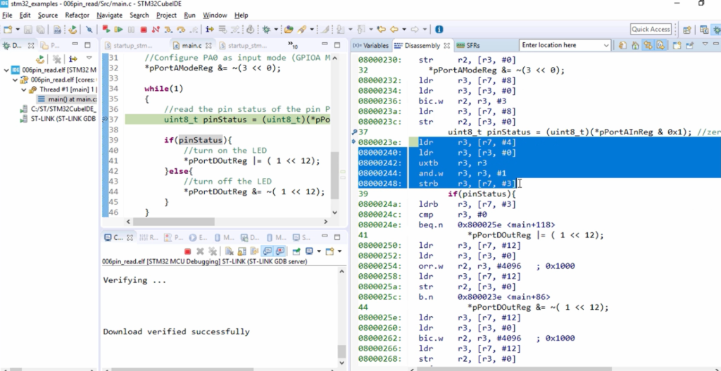
We will investigate the disassembly of the below code.
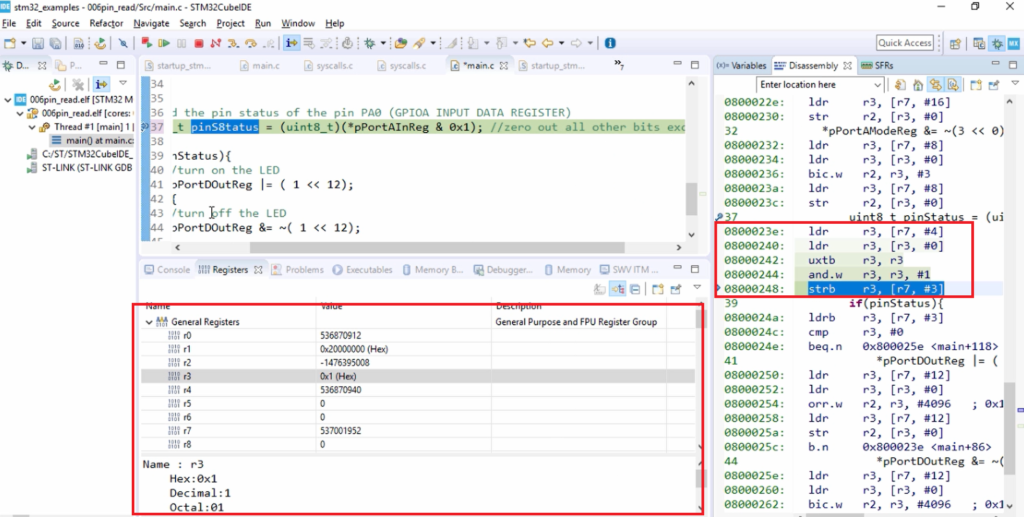
uint8_t pinStatus = (uint8_t)(*pPortAInReg & 0X1);
Here, what’s happening?
First, the data will be loaded into the r3 register from pPortAInReg(this memory location). That is 40020010. So, r3 is loaded with the input port A input data registers address and from there value will be read and it will be populated in r3.
You can even see that in the register tab. After you do some post-processing, you can find that r3 is 1. So, now r3 is 1. After that what happens? The value of r3 will be stored in the pinStatus variable. That’s why ‘strb’ is executed.
ldr r3, [r3, #0] – This is load from the input data register and stored to the variable (strb r3, [r7, #3]).
That means a code is behaving as expected. For each iteration of this loop, value will be read from *pPortAInReg & 0X1 this memory location and it will be populated.
Please note that: For each iteration of the loop, the current value will be read from the peripheral register address [input data register of GPIOA], and variable pinStatus will be updated.
For each iteration, the fresh value will be read from the input data register and r3 will be updated. So, that is very important. That means for every iteration processor obtains the fresh value from that memory location and it populates the register r3, and the r3 value will be saved into this variable. So, it happens for every loop. So, that is very important.
Why?
Because the user can change the value of the pin at any time. That’s why, every time the processor should read the fresh value from the port A input data register and the processor should update the corresponding variable, that is pin status in this case. So, that’s why you can see that for every iteration the load and the store will get executed.
O2 optimization
Please note that debugging at the O2 level is not that easy, because there will not be a one-to-one mapping between the disassembly and the source code what you have written.
For example, let’s say if I try to execute step over, it looks like the execution is taking place in a random fashion. So, sometimes it goes inside the while loop, and sometimes it comes out of the while loop like that.
You can see that, we are trapped in the while loop, and here we can see that it is not actually executing the below line
uint8_t pinStatus = (uint8_t)(*pPortAInReg & 0x1);
This code depends upon the old value of the pin status. So, that’s the reason why our code is not working.
So, the pin status is updated maybe only one time in the code and after that, the processor is keep reusing that without reading the fresh value from the Port A input data register.
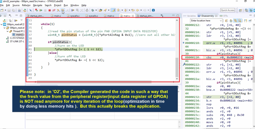
You can also check the disassembly code here on the right-hand side. Here it is comparing whether the pin status is zero or not. For that, it is using the instruction cbz. cbz stands for compare and branch on zero.
If r0 is really 0, the code will jump to the 0x8000232 location. But r0 is not getting updated, so that’s a problem. So, r0 is always 0.
It is not getting updated. So, the processor is not visiting the required address and it is gathering the fresh value from the address, that is from pPortAInReg this address. So, that’s how the compiler optimized the code for you.
It actually avoided the processor visiting that memory location again and again and acquiring the new value, which means it reduced the number of memory hits. When you reduce the memory hits, your code becomes faster.
So, the compiler try to make your code more faster by decreasing the amount of memory hits. That may be a good idea of the compiler but that actually breaks your application.
That means we have to now tell the compiler that don’t do any optimization on this (pPortAInReg) particular address.
How to tell that?
”Welcome to the word of volatile”.
We can tell the compiler not to do any optimization on the address by using the volatile type qualifier.
We’ll understand in the next article maybe how to fix this problem using a volatile type qualifier. But before that, we have to understand what exactly volatile does.
FastBit Embedded Brain Academy Courses
Click here: https://fastbitlab.com/course1