LCD SPI initialization coding part-3
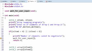
Here, instead of writing GPIO_MODER_MODE7_Pos (Figure 1), you can use the LCD_RESX_PIN macro. However, you have to multiply it by 2 (Figure 3).

You can use the LCD_RESX_PIN macro because it is set to GPIO_PIN_7.
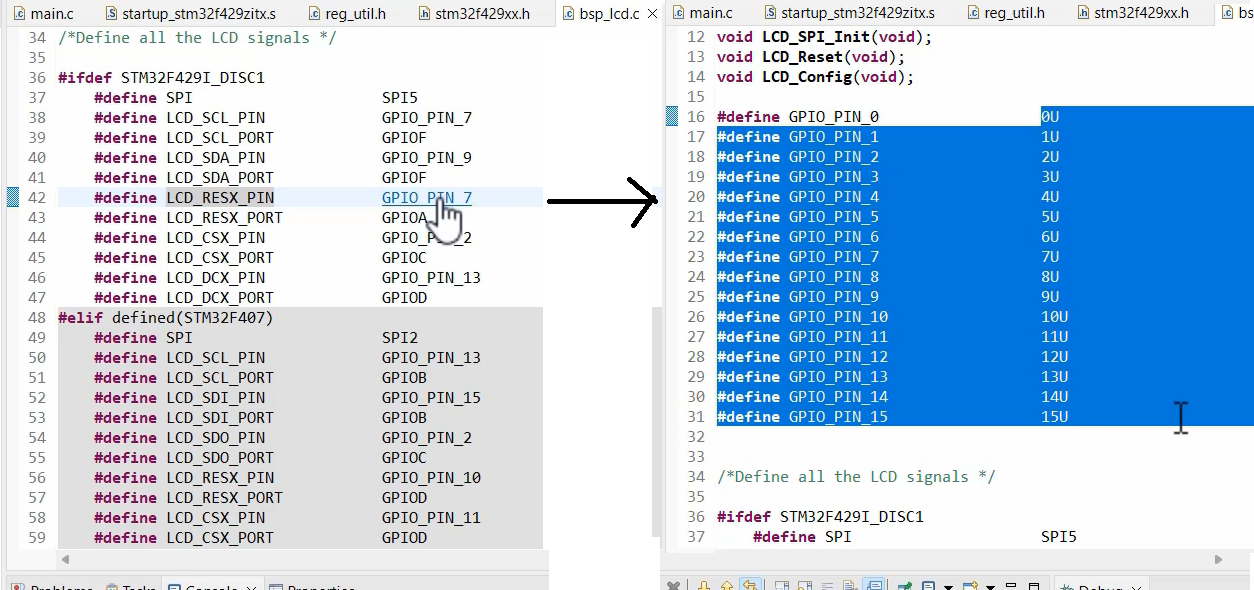
Make sure to define these macros (as shown in Figure 2). The GPIO_PIN_0 macro should be set to 0. Therefore, you need to write these macros from 0 to 15 and define them with the corresponding values (as shown in Figure 2).
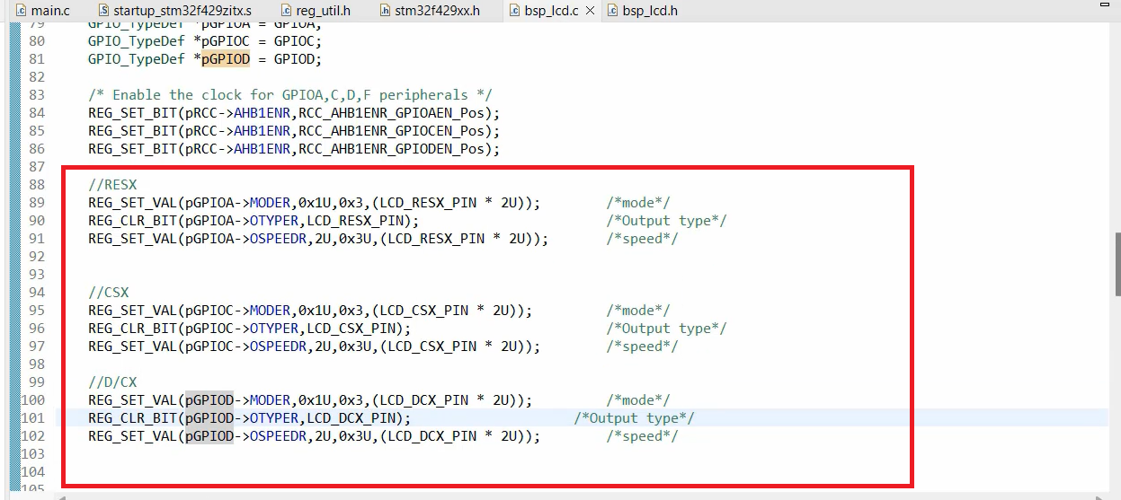
We have just finished initializing our reset pin. For the other two pins, CSX and D/CX, you can use the same method. The code for CSX and D/CX is shown in Figure 3.
FastBit Embedded Brain Academy Courses
Click here: https://fastbitlab.com/course1

