LCD SPI initialization for STM32F407x+External LCD
In the previous article, we wrote code to initialize pins and the SPI peripheral for the STM32F429 board.
In this article, we will focus on coding the initialization of the LCD SPI for the STM32F407x board with an external LCD connected to it.

The interface is pretty much the same as the previous one. The only difference that I can see here is that, in the previous interface, we used only one single line for bidirectional SPI communication. However, when interfacing an external LCD with the STM32F407 Discovery board, you need to use two separate lines for bidirectional communication. These lines are SDI (also known as MOSI) and SDO (also known as MISO). Let’s use these terminologies.

Let me now show you the code for initializing the pins and the SPI peripheral. All of these functions are called from the BSP function.
Go to bsp_lcd_init, in the LCD_pin_init function, I used PIN initialization for SDI and SDO, 2 separate pins. Or you may just use one line as a bidirectional line. That is also fine. (as shown in Figure 3).

In the lcd_pin_init function, I used PIN initialization for SDI and SDO, 2 separate pins. Or you may just use one line as a bidirectional line. That is also fine. (as shown in Figure 3).
Let’s examine lcd_spi_init (as shown in Figure 4). This code initializes the SPI peripheral. As you can see, I have cleared the BIDIMODE because I am not using that mode.
REG_CLR_BIT(pSPI->CR1, SPI_CR1_BIDIMODE_Pos); /* 2 lines uni directional lines */
And also SPI clock or SPI baudrate what I’m using here is 21MHz. So, I just used 0 here. That means, the divider will be 2. So, 42MHz divide by 2, which is equal to 21MHz as SPI clock.
REG_SET_VAL(pSPI->CR1, 0x00U, 0x7U, SPI_CR1_BR_Pos); /* SPI clck = 42MHz/2 –> 21MHz */
This code sets a value of 0x00U in bits 0 to 6 (0x7U) of the register CR1 in the SPI peripheral (pSPI), at position SPI_CR1_BR_Pos, resulting in a SPI clock frequency of 21MHz (calculated from a system clock of 42MHz divided by 2).

All those functions are called from the BSP function, that is bsp_lcd_init(as shown in Figure 5).
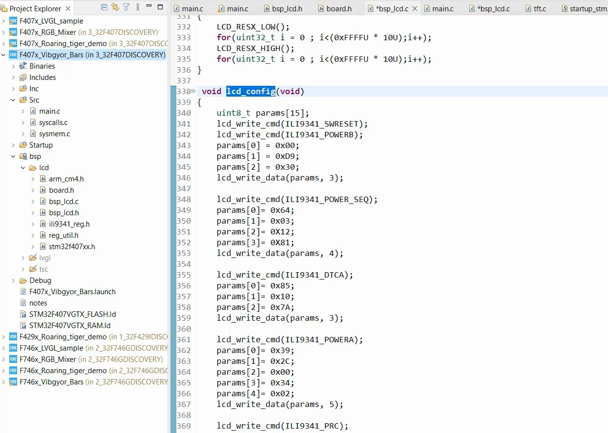
After that, the bsp_lcd_init also uses the lcd_config function which sends various LCD commands. The lcd_config used for this board, that is STM32F407x board with external LCD is a little different compared to the STM32F429 Discovery Board.

After that, that is one more function to send the command parameters lcd_write_data. Here I did a small modification, as shown in Figure 7.

As per the LCD datasheet, you can assert the chip select, which means, you make it low. When you make it low, LCD will be enabled to receive the data and you pump all the data out and then you make sure that SPI is not busy doing TX, and then you can deassert only one time instead of repeatedly doing that inside the for loop. So, you can use the above-modified code.
If you are using the STM32F746 board, there is no need to configure the LCD device by sending any commands. SPI communication is unnecessary.
FastBit Embedded Brain Academy Courses
Click here: https://fastbitlab.com/course1


