GPIO output mode with push pull state
GPIO (General Purpose Input/Output) pins on microcontrollers or single-board computers can be configured in various modes including input, output, and alternate function modes.
When configured as an output, GPIO pins can be set to operate in either push-pull or open-drain mode. In push-pull mode, the GPIO pin can both source (provide current) and sink (draw current) current, while in open-drain mode, the pin can only sink current.

The push-pull state is the default configuration of any GPIO pin in output mode. When you enable GPIO port by default, its pin will be in input mode. But if you set any pin as the output mode, then by default it will be in push-pull configuration.
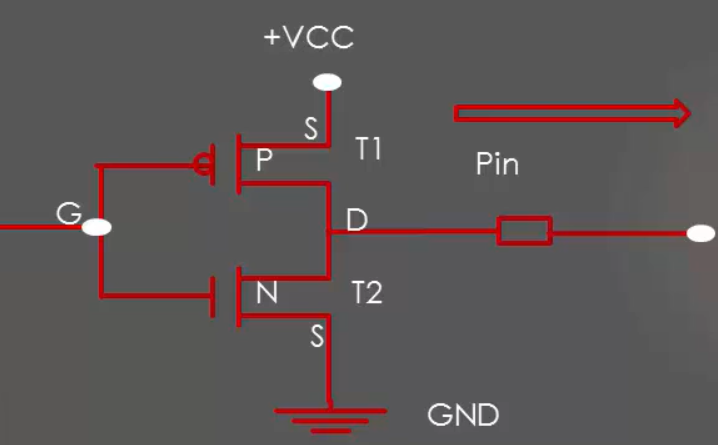
The name Push-pull output configuration because output will be pulled actively between low and high by using two transistors.
Push-pull configuration doesn’t need any pull-up/pull-down resistor. Push-pull output uses two transistors. Each will be on to drive the output to the appropriate level.
From Figure 1. The top transistor will be ON when the output has to be driven high. The bottom transistor will turn ON when the output has to go low.
The exact method for configuring a GPIO pin in push-pull output mode can vary depending on the specific microcontroller or single-board computer you are using. It’s always a good idea to consult the documentation for your particular device to ensure you’re using the correct registers and settings.
In the following article, let’s learn Optimizing I/O power consumption.
FastBit Embedded Brain Academy Courses,
Click here: https://fastbitlab.com/course1


