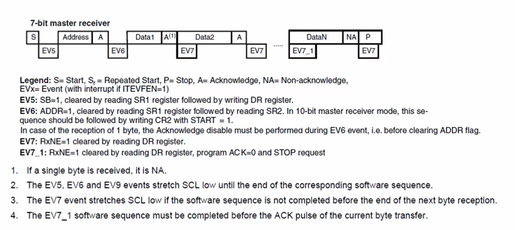
I2C transfer sequence diagram for master receiving data
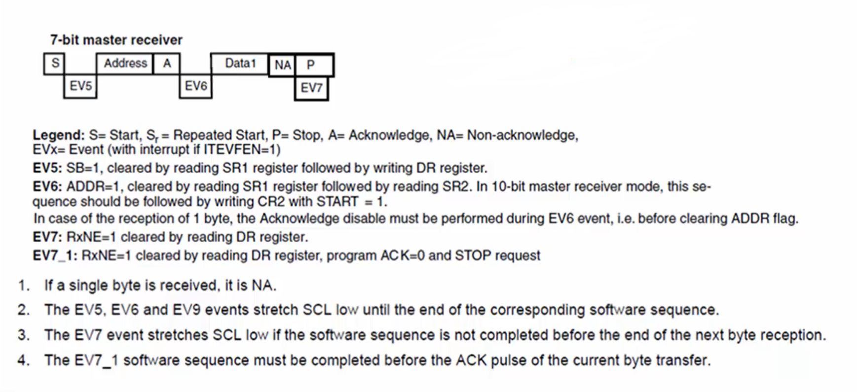
In this article, let’s understand the implementation of the I2C_MasterReceiveData API. Refer to the transfer sequence diagram for the master receiver (Figure 1) in the reference manual of the microcontroller before understanding how the master receives data from the slave.
How does the reception happen?
Let’s understand the master reception process with the help of Figure 1.
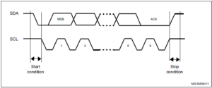
- Every I2C transaction begins with the start condition, which is generated by the master device.
- The EV5 happens, and event EV5 is nothing but the setting of the SB flag in the status register. This indicates that the start generation was successful. When SB is set, the SCL will be stretched. The SCL will be pulled to low until the SB flag is cleared.
- Master performs the address phase. In the address phase master sends the 7-bit address and a read/write bit. In this case, the read/write bit is 1 since the master is receiving the data from the slave.
- The slave will send the ACK after receiving the address. The slave ACKs the address if the valid slave is present on the bus.
- If the address phase is successful, then EV6 will be set, which means the event EV6 will happen. Ev6 means the setting of the flag ADDR and clock will be stretched to low until the software clears the ADDR flag.
- Once the software clears the ADDR flag, the data reception will happen. The shift register of the master will be getting filled with the data bits sent by the slave. That means the master will start receiving the data from the slave, and after receiving one complete byte in the shift register, the master will send Ack to the slave. This ACK is a master to slave ACK.
- After receiving the ACK, the RXNE flag will be set, or it becomes 1, and EV7 will occur, indicating that the receive buffer is not empty. The receive buffer is currently filled with the data byte received from the slave. When RXNE is set, it is the confirmation for the software to read the data byte from the receive buffer.
- Observe Figure 1. Even though the RXNE is set, the shift register is receiving the next byte from the slave. EV7 and Data2 are parallel, as shown in Figure 1. After receiving the second byte, the master will again send the ACK to the slave, and the software will read the data from the receive buffer.
- The master code should read from the data register of the I2C peripheral only if the RXNE flag is set. Otherwise, you cannot read the data.
- After receiving the last byte, the master sends NACK instead of ACK. When a slave receives NACK, it will understand that the master doesn’t want more data. Remember that the NACK is the indication to the slave to stop sending data. Whenever a slave receives NACK, it stops sending data.
- Then master generates the stop condition, and it also reads the last byte which is received.
These are all the steps involved in master reception. It is necessary to pay attention to the flags which have the capacity to stretch the clock to low. Whenever the clock is stretched to low, both master and slave are in a wait state.
Remember that the ACK sent by the master is an indication for the slave to send one more byte. Therefore, Data2 comes after the ACK (Figure 1). If the master sends NACK after receiving Data1, then Data2 will not appear from the slave.
Remember one more thumb rule: read the data from the data register only when the RXNE flag is set. Otherwise, don’t try to read the data register.
Let’s understand the master reception with some examples. Let’s see how the master reception is achieved in the following cases:
1. Case 1: Master receiving only one byte from the slave (Figure 2).
- Master generates the start condition.
- Master code clears the start bit flag.
- Master sends the address of the slave.
- The slave will send the ACK after receiving the address.
- ADDR flag is set. When the ADDR flag is set, the clock is stretched, and both master and slave are paused.
- Before clearing the ADDR flag, disable the ACKing and then program the stop bit of the control register.
- Clear the ADDR flag. When you make ADDR as zero, the clock will be released, and data reception begins. Since you have already programmed ACK is equal to zero, NACK will be sent to the slave, and it stops sending more data.
- The I2C hardware will automatically generate the stop condition since the stop bit is programmed to 1.
- Confirm RXNE =1 and read the data from the data register.
Be careful while controlling the ACK bit.
2. Case 2: Master receiving more than one byte from the slave. Consider that the master wants to receive 6 bytes, so the length is equal to 6 bytes (Figure 3).
- Master generates the start condition.
- Master sends the address of the slave.
- The slave will send the ACK after receiving the address.
- ADDR flag is equal to 1.
- Once you clear the ADDR flag, the master receives the first byte and sends the ACK to the slave.
- The master code waits until RXNE is equal to one. When RXNE=1, the master code reads first data, i.e., Data1, and parallelly Data2 will be received from the master, and the ACK for that will be sent. Then the master reads the second byte from the data register.
- Similarly, Data3 and Data4 will be received and read from the data register.
- In the software, you have to count the length. Before reading the data, initially, the length will be 6, and it is decremented by one after each byte transfer.
- After reading the Data4 from the data register, the length becomes 2. When length = 2, program the ACK=0 and STOP=1. This is a procedure to receive the last two bytes.
- Read Data5. After reading Data5, the length will become 1, meaning that only one byte is pending.
- Since the ACK is programmed to zero when the length is equal to 2. For the last data byte or Data6, NACK will be sent instead of ACK.
- Since the stop bit is programmed to 1, the stop condition will be generated by the master.
- Read the last byte from the data register.
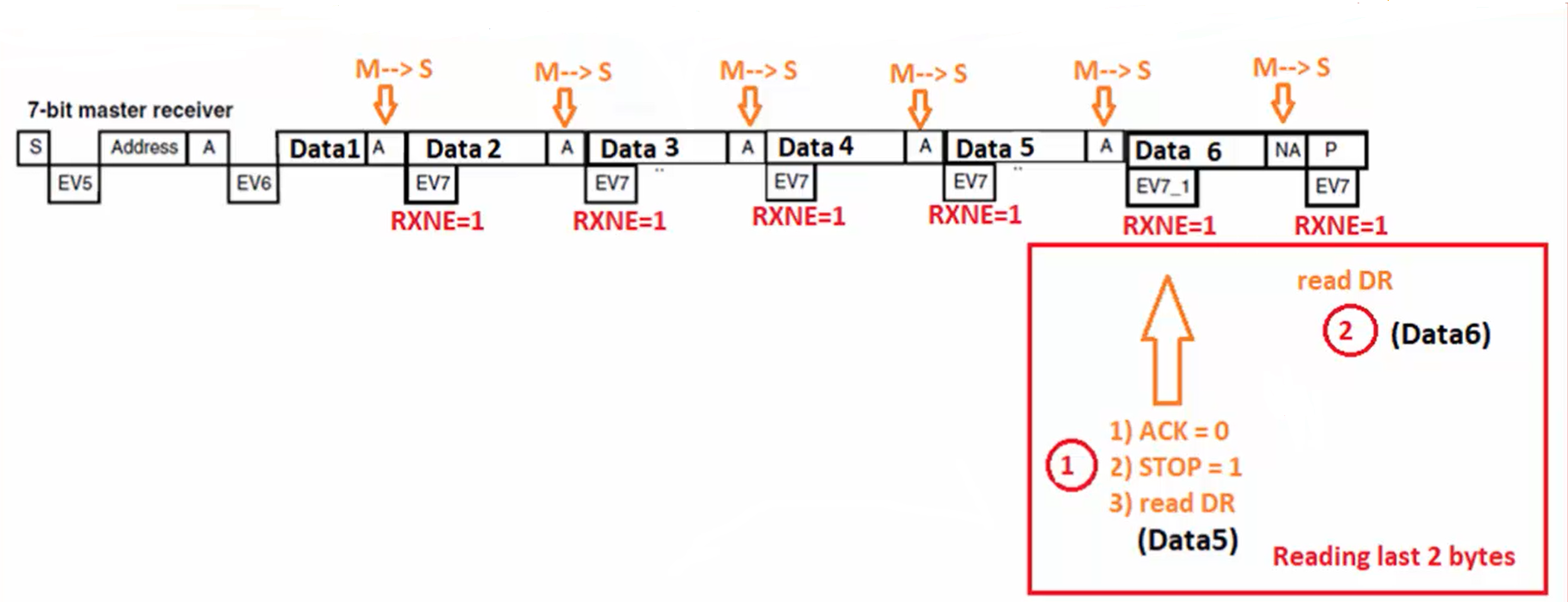
When the master is receiving more than 1 byte, then if length = 2, make ACK = 0, STOP =1, and read the data. When you make ACK = 0, STOP =1, it sends NACK to the last data byte which is received. This is a thumb rule, and it states that sending the ACK for the last data byte received is wrong.
If the ACK is sent, the slave will try to send one more data that is not required for us. The length is 6 bytes here, so you should not receive more than 6 bytes from the slave. Therefore, don’t provoke the slave by sending an ACK. Instead, send NACK.
The right point to reset the ACK bit of the control register is detected by the length variable which you manage in your code.
In the following article, let’s do the Assignment: I2C master receive data API implementation.
FastBit Embedded Brain Academy Courses
Click here: https://fastbitlab.com/course1

