Configuration options and USART registers
In the usart_driver.h file, in the beginning, mention the device specific header file (Figure 1).

Figure 2 shows the configuration and handle structure for the USART peripheral.

All the prototypes are copied into the driver.h file, as shown in Figure 3.

Mention the usart_driver.h header file in the usart_driver.c (Figure 4).

Include the usart_driver.h at the end of the MCU specific header file (Figure 5).

In the driver.c file, you must implement peripheral control, peripheral clock control, and other APIs, as shown in Figure 6 and Figure 7, respectively.


Now let’s go to the usart_driver.h file to discuss the options to configure the configuration structure.
USART_Mode: In order to configure the USART mode, the user application can use the macros shown in Figure 8, which you can get from the file USART_API_prototype.h attached in the resource section. 0, 1 and 2 are the codes for USART_MODE_ONLY_TX, USART_MODE_ONLY_RX and USART_MODE_TXRX macros.

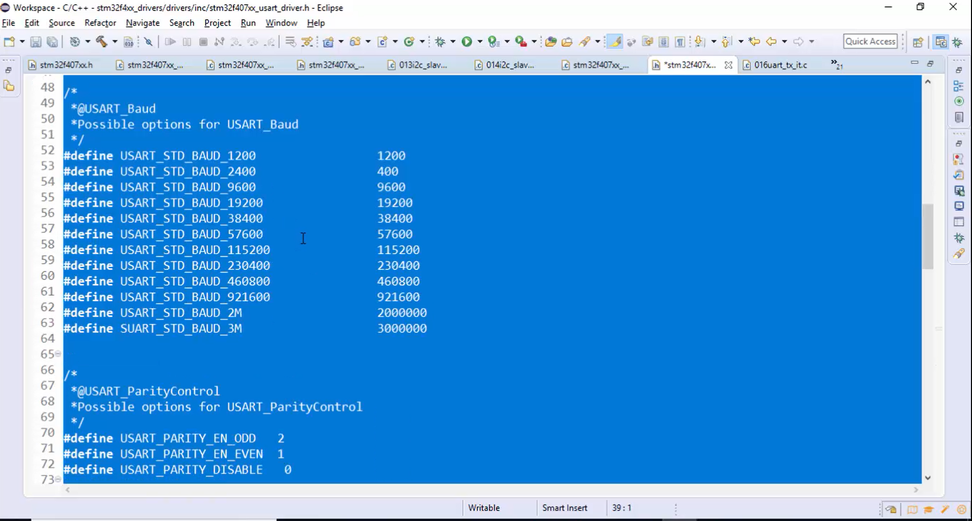
USART_Baud: The standard baud rate values from 1200bps to 3Mbps (Figure 9) can be used to decide the baud rate value. The USART baud macros can be selected by going through the baud rate generation table of the USART peripheral mentioned in the reference manual.

In the reference manual, go to the functional description section of the USART peripheral, there you will get a fractional baud rate generation section (Figure 10).

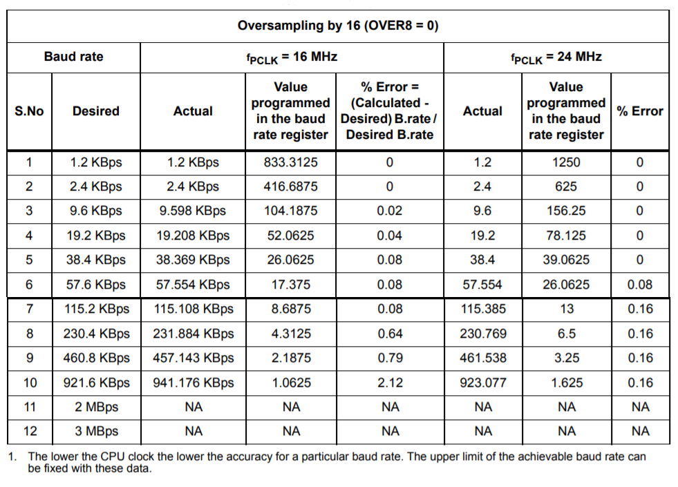
As you browse through this document, you will get a table shown in Figure 11. Since our peripheral clock is 16MHz, we have to use this table for baud rate calculation.
In Figure 11, you can see that if the peripheral clock is 16MHz, then it is possible to reach up to 3Mbps. Since the baud rates in Figure 11 are standard baud rates, they are coded as C macros.
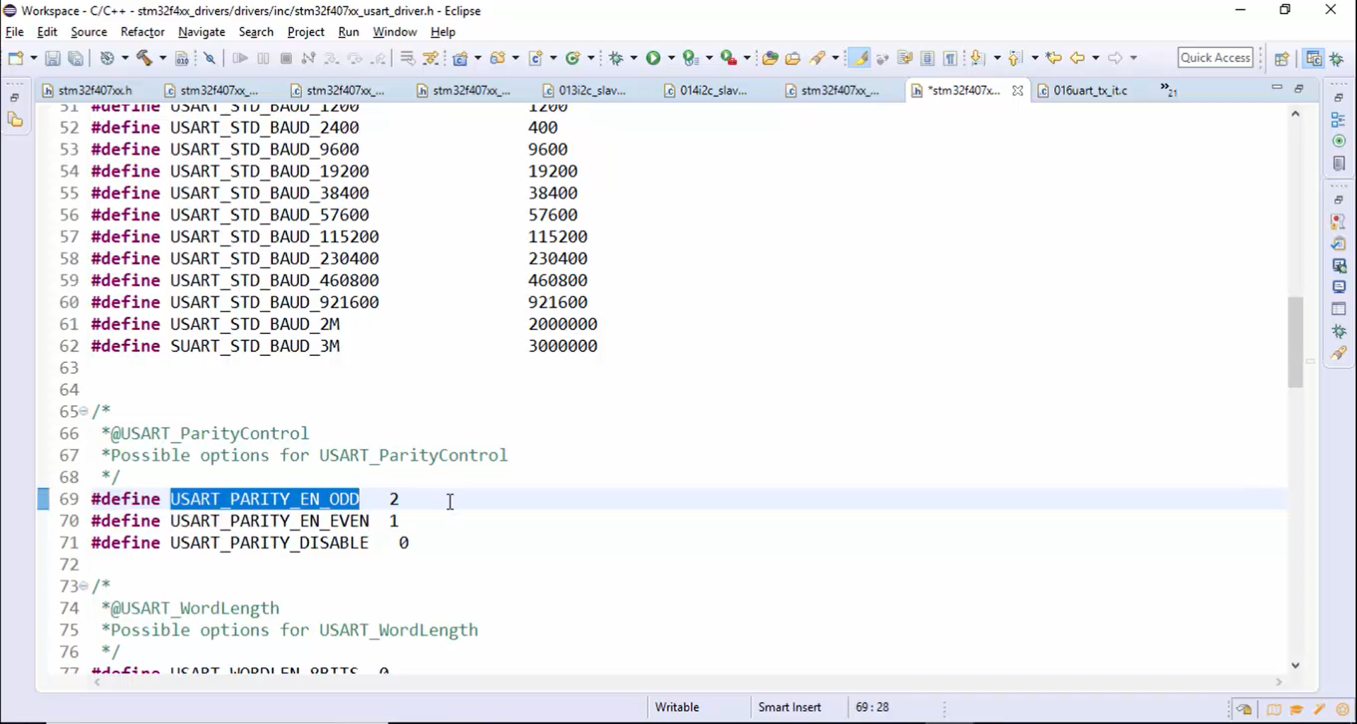
USART_ParityControl: There are three options (Figure 12) for parity control. One is USART_PARITY_DISABLE, then USART_PARITY_EN_EVEN, and another is USART_PARITY_EN_ODD.
USART_WordLength: There are two choices for word length, either 8 bits or 9 bits. Therefore, you can use two macros, as shown in Figure 13, to configure the word length.
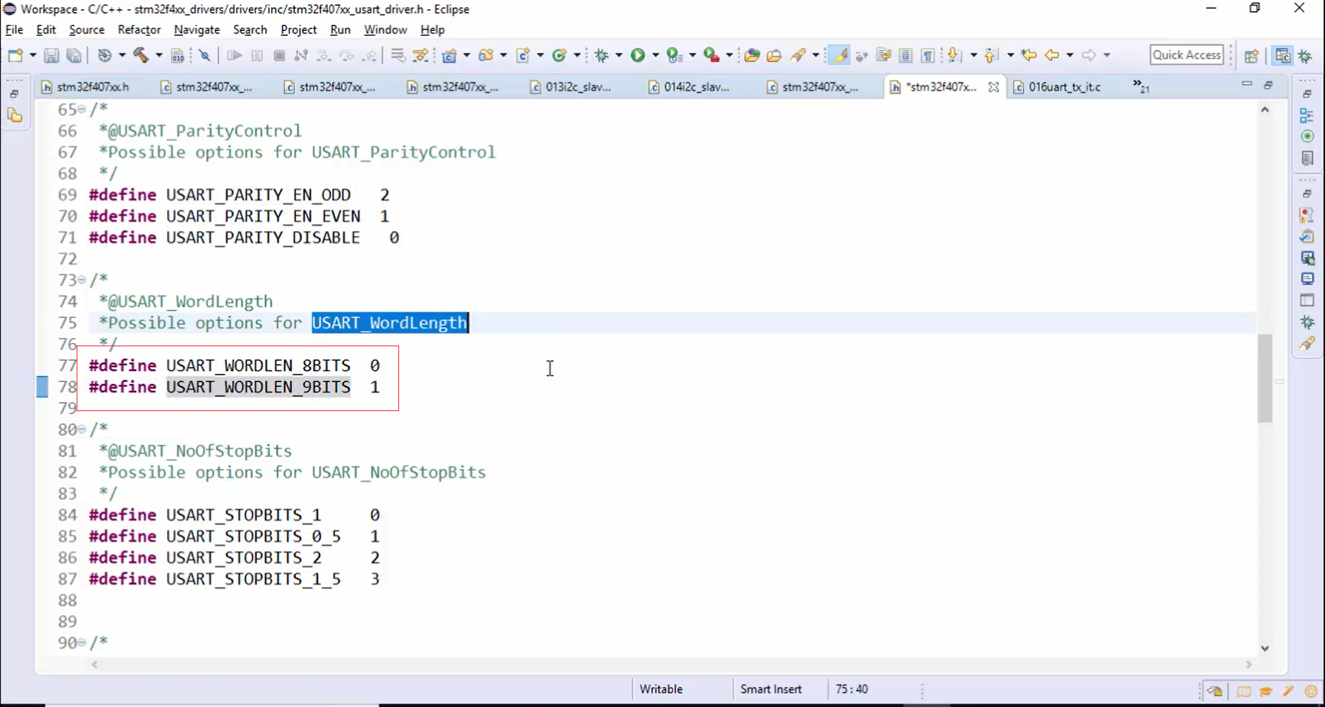
USART_NoOfStopBits: There are four options for the number of stop bits, as shown in Figure 14. They are only one stop bit, 0.5 stop bit, 2 stop bits, or 1.5 stop bits.
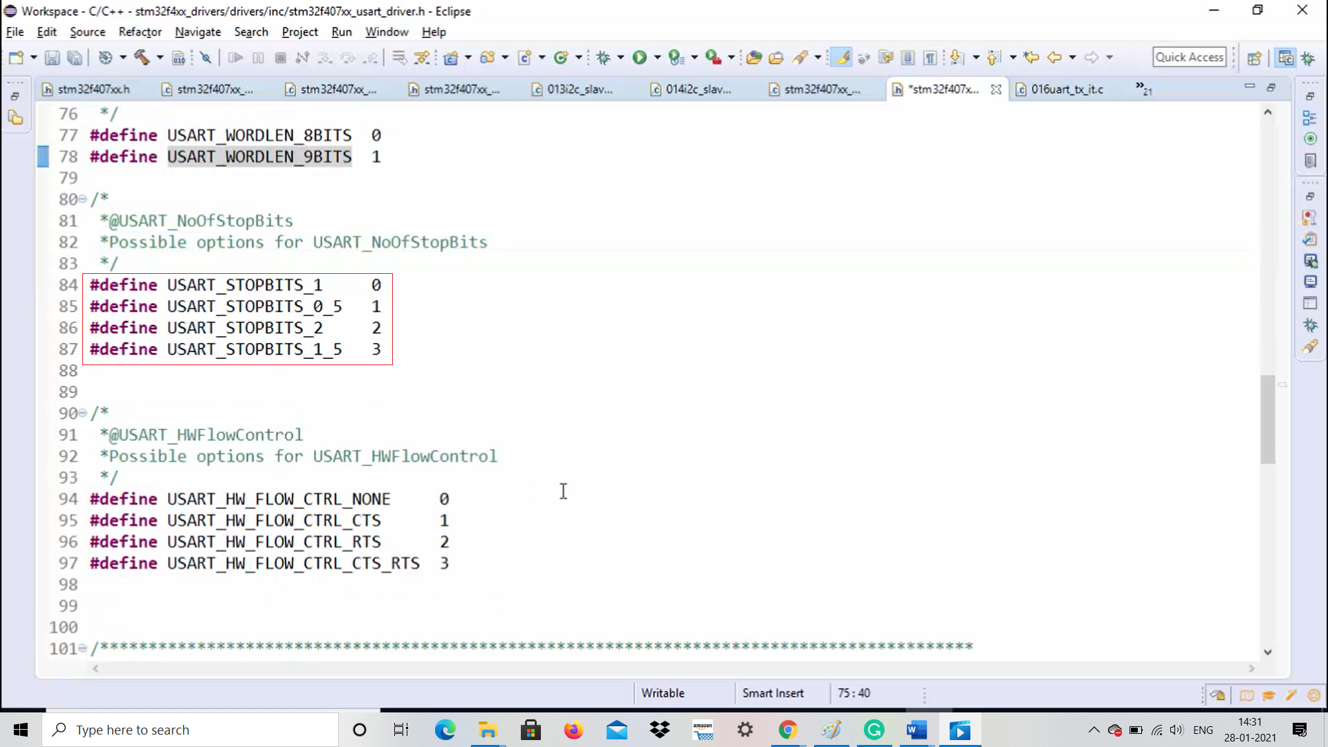
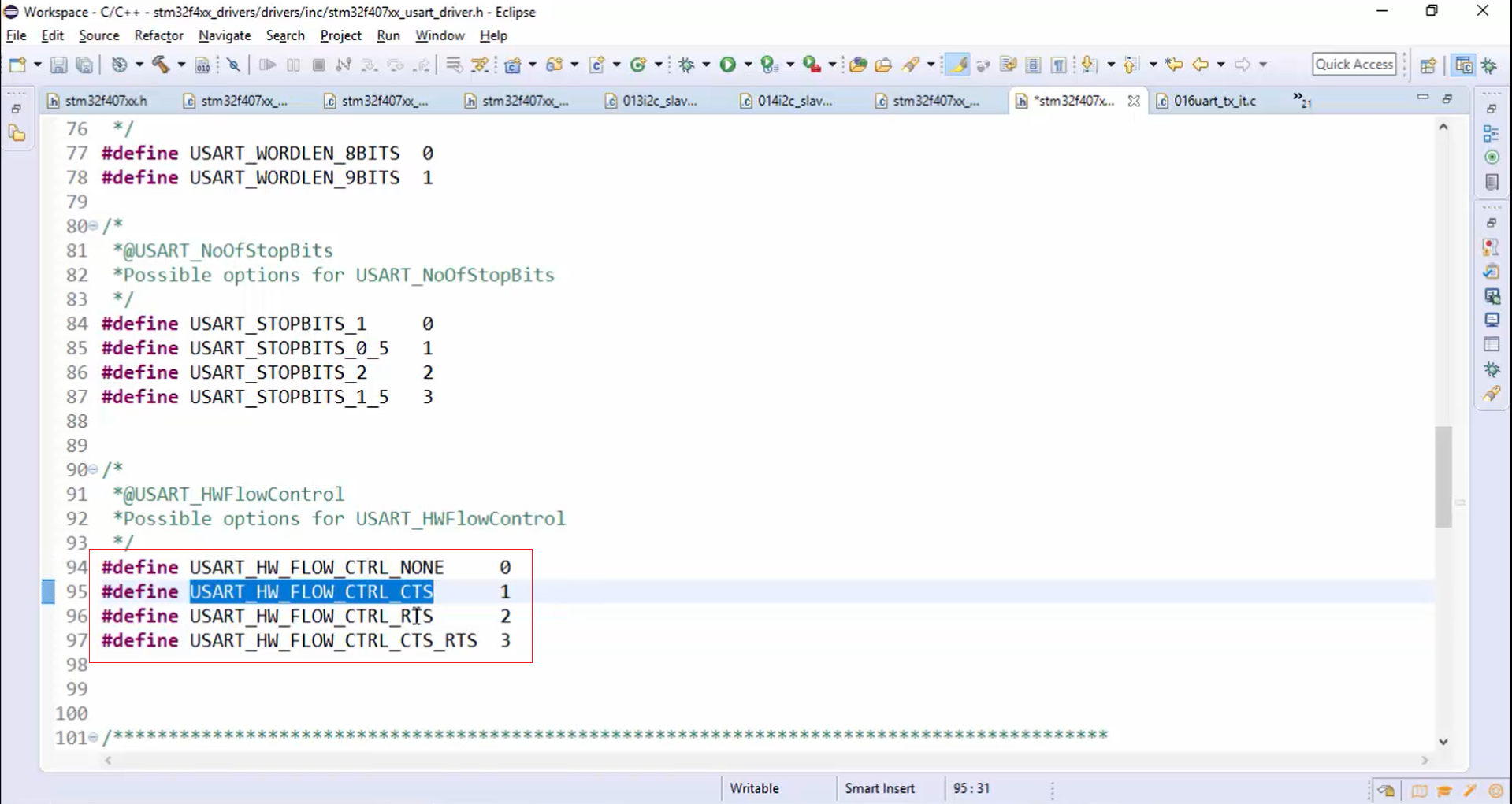
USART_HWFlowControl: Hardware flow control none, hardware flow control CTS, hardware flow control RTS and hardware flow control both CTS and RTS are the macros used to configure the hardware flow control (Figure 15).
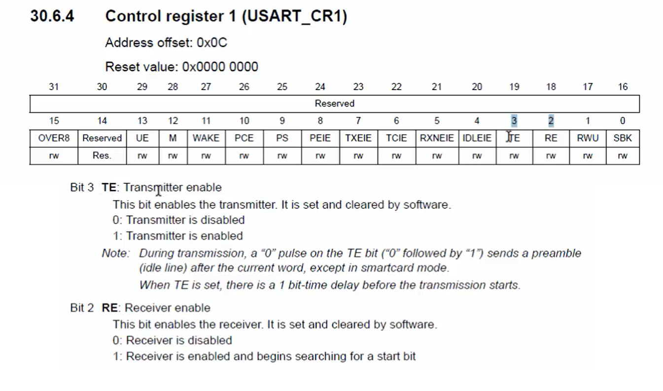
Where to configure the USART_Mode?
The USART_Mode can be configured by enabling or disabling bits 2 and 3 of the CR1 register (Figure 16). Bit 2 is receiver enable, and bit 3 is transmitter enable.
If you want to configure the microcontroller only to transmit the data over the USART peripheral, then you need to enable the transmitter, not a receiver, thereby saving some power.
If you only want receive data, then you can use the receiver enable bit by turning off the transmitter. If you want it to be involved in both transmission and reception, then you can turn on both bits 2 and 3.
Where to configure the USART_Baud?
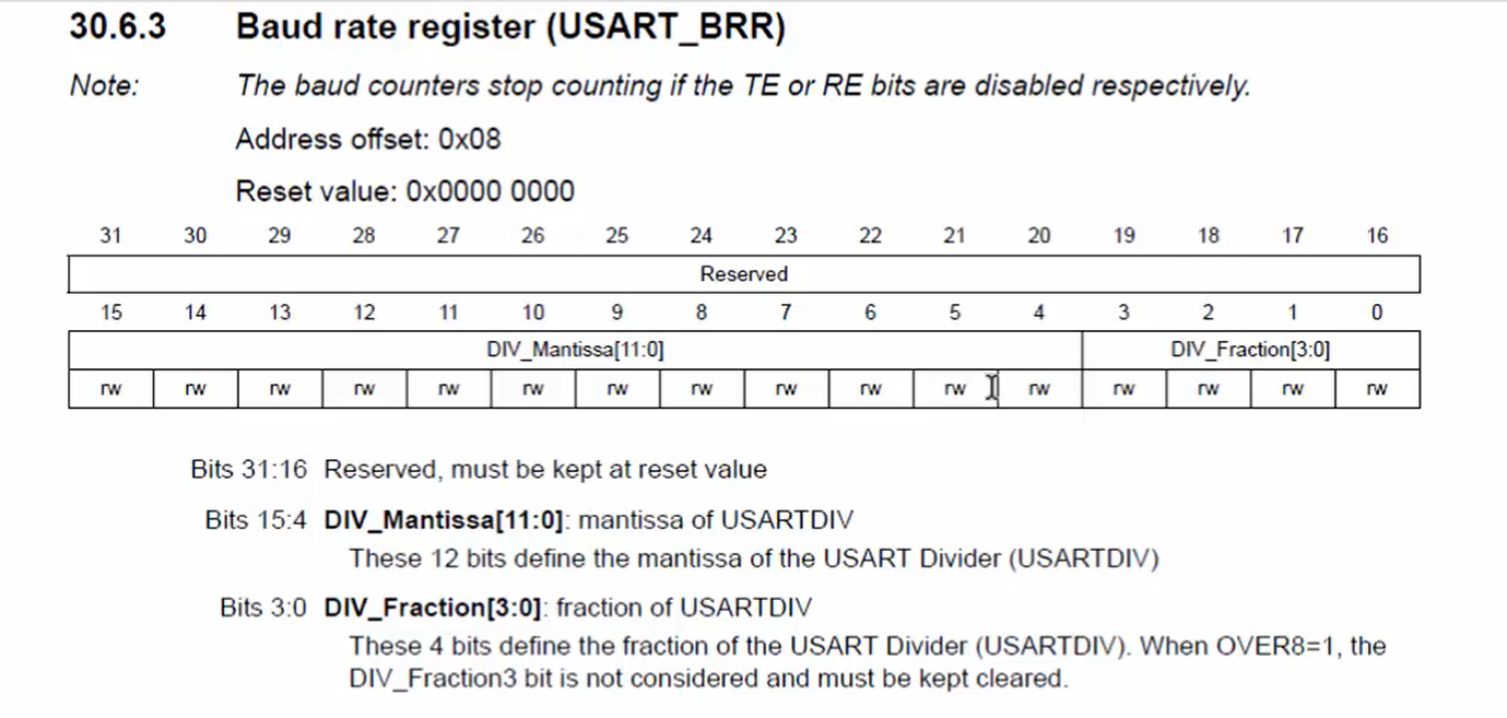
Remember that, to configure the baud rate, you have to properly configure the mantissa and fraction part of the USART_BRR register shown in Figure 17 according to the baud rate you want to use.
Where to configure the USART parity control?
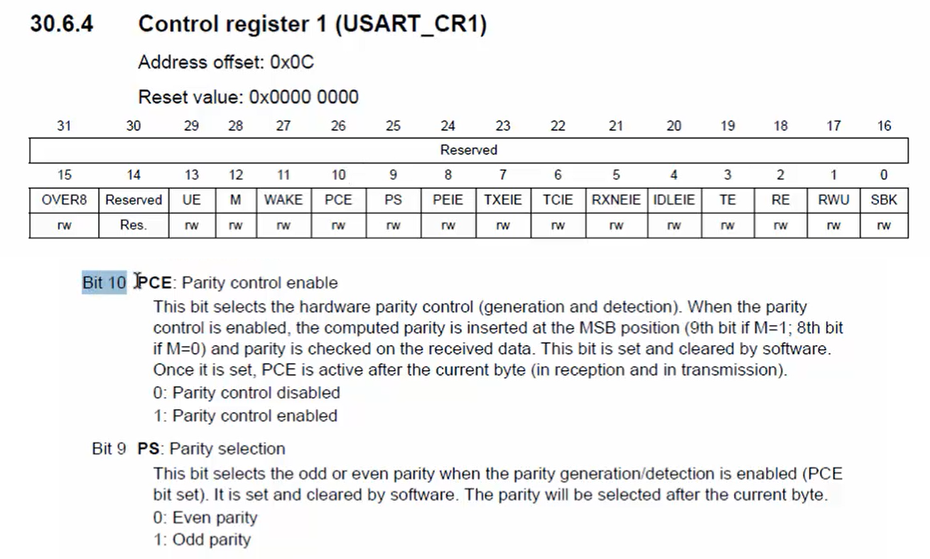
You have to configure bits 9 and 10 of the CR1 register (Figure 18) in order to control the parity. The bit number 10 is disabled by default. Once you enable the bit number 10, the parity control will be enabled. Bit 9 can make sense only when the parity control is enabled. By using bit 9, you can configure either even parity or odd parity. By default, it will be even parity.
Where to configure the USART word length?
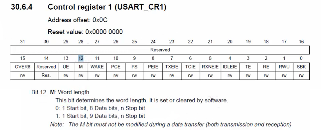
The word length can be configured in the bit number 12 of the CR1 register (Figure 19). The 12th bit of the CR1 register determines the word length, and it is set and cleared by the software. If this bit is zero means one start bit, 8 data bits, and n stop bits. Here the n will be decided later by using another control bit. If it is 1, then it means 1 start bit, 9 data bits, and n stop bits.
Where to configure the number of stop bits?
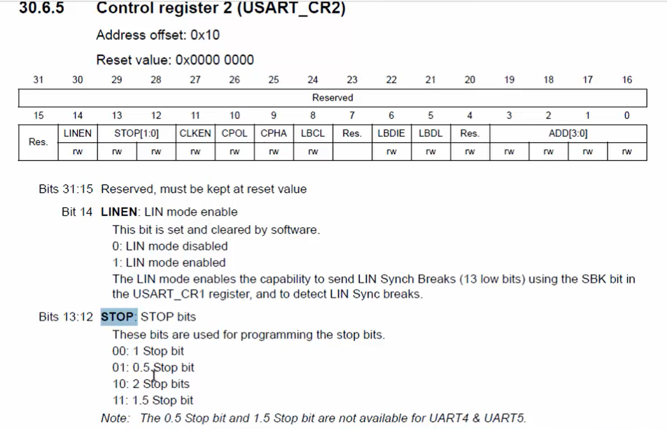
The number of stop bits can be configured in the CR2 register (Figure 20). There are 4 options for configuring stop bits. They are:
- 1 stop bit.
- 0.5 stop bit.
- 2 stop bit.
- 1.5 stop bit.
You can use any of these four options.
If you use a higher baud rate (3Mbps or 4Mbps), then it’s better to use more stop bits to give some time for the receiver to interpret the data properly. Usually, we use 2 stop bits in a higher baud rate situation. If the baud rate is lesser, like less than 1Mbps, then you can use 1 stop bit. When the baud rate is lesser than or equal to 9600bps, you can use 0.5 stop bit.
Where to configure the hardware flow control?
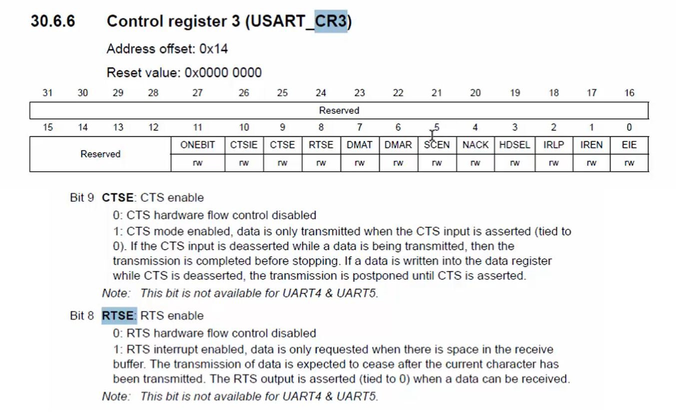
The hardware flow control can be configured in a CR3 register by going through bit 8 and bit 9 (Figure 21). If you enable bit 9, then the CTS will be enabled. If you enable bit 8, the RTS line will be enabled, and if you enable both the bits 8 and 9, then both CTS and RTS lines will be enabled.
Exercise:
Write the macro definition for all the macros shown in Figure 22 in order to initialize the configuration structure.
In the following article, let’s see USART Driver API: USART Init.
FastBit Embedded Brain Academy Courses
Click here: https://fastbitlab.com/course1

