Atmega328p Timer peripheral explanation
In this article, let’s understand ATmega328P microcontrollers Timer peripheral because we will be using the Timer ISR to attract time in our application.
Before that, we already have these variables or these attributes in our main structure(Figure 2).
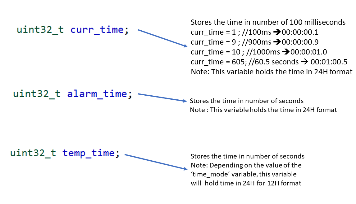
- curr_time: In this application, the current time variable stores the time in a number of 100 hundred milliseconds. That means this variable will be incremented for every 100 milliseconds by the Timer ISR.
For example, if curr_time = 1, that means 100 milliseconds has been elapsed, then the display would show like this → Hour 0, minutes 0, seconds 0, the sub-second field will show 1, which signifies 100 milliseconds.
If current time = 9, that means 900 milliseconds. That is 9 * 100 milliseconds, that is 900 milliseconds, then the display would show like 00:00:00.9.
If current time = 10, that means, 10*100 milliseconds, that means 1 second. Then, the sub-second field will show 0, and the second field will show 1.
If the current time = 605, that means 60 into 5 seconds. 60 seconds means 1 minute. That’s why the minute field will show 1, and .5 seconds means 500 milliseconds; that’s why the sub-second field will show 5, like that.
Please note that the curr_time variable holds the time in 24-hour format.
- alarm_time: This stores the time in the number of seconds. Because we manipulate the alarm_time in terms of hours, minutes, and seconds, we don’t care about the subsecond field. That’s why it stores the time in the number of seconds, and the alarm_time variable holds the time in 24-hour format.
- temp_time: Temporary time variable stores the time in the number of seconds because we don’t edit or we don’t set the subsecond field. We only modify hours, minutes, and seconds; that’s why this also stores the time in the number of seconds. So, depending on the value of the ‘time_mode’ variable, this variable may hold time in 24-hour format or 12-hour format.
We’ll see while coding how to use these variables.
This is just for information. And, curr_time and alarm_time variables hold the time in 24-hour format. When you hold the time in 24-hour format, you would need not use one more variable to hold the time format, like AM or PM. Because, by decoding the 24-hour format, we can know whether it is AM or PM. So, that is one advantage of storing the time in 24-hour format.
Now, let’s explore the timer peripheral. The ATmega328P has 3 timer and counter peripherals. Timer/Counter0, Timer/Counter1, and Timer/Counter2. The Timer/Counter0 peripheral is already used by the millis functionality of the Arduino framework.
Let’s open the datasheet of the ATmega328P microcontroller to know more about the timer peripherals.
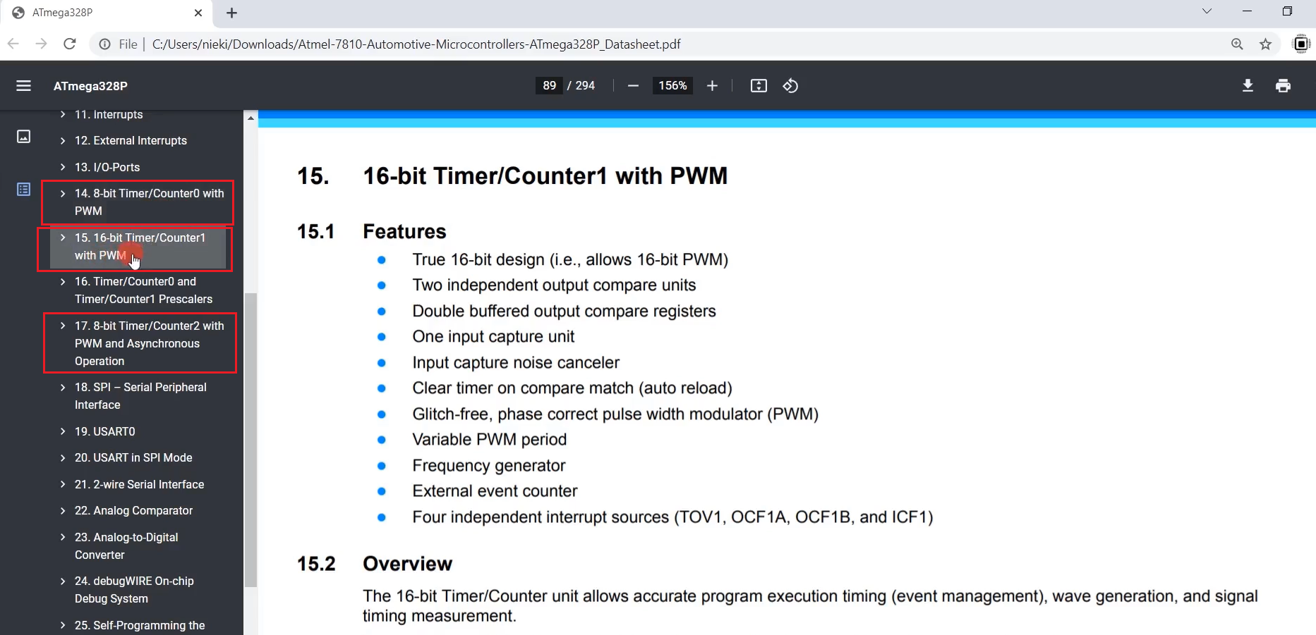
Figure 3 shows the datasheet of the ATmega320P microcontroller, and here you can see that it has three timers and counter peripherals. One is 8-bit Timer/Counter0, another one is 16-bit Timer/Counter1, and another timer peripheral is 8-bit Timer/Counter2.
The Timer/Counter0 and Timer/Counter2 are 8-bit timers, and the Timer/Counter1 peripheral is a 16-bit timer.
The Arduino framework already uses an 8-bit Timer/Counter0 peripheral to implement the millis functionality. The millis variable is updated using the overflow interrupt of the 8-bit Timer/Counter0 peripheral. So, we will not be using that peripheral; we will use a 16-bit Timer/Counter1 peripheral.
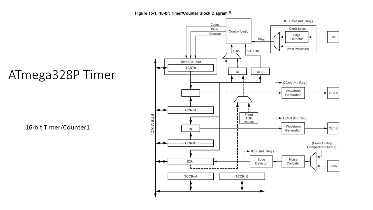
You can see the block diagram of this 16-bit timer in Figure 1. And here, the important thing that we should notice is the Timer/Counter field. This is where counting takes place, which is driven by the counter clock(clkTn). clkTn is a counter clock or timer clock. And this is again derived from this clock selection engine, so you can supply a special clock to tick the timer. You know, you can provide the clock via the external pin of the microcontroller. So, I will not be using this method.
What we will use is, we will use the main system clock of the microcontroller, and we can slow down that clock using this Prescaler. Basically, we’ll use the clock through this way. You can use a Prescaler to slow down the clock to increase or decrease the timer resolution. We will explore more on that later.
And this timer also has two compare registers. Whenever the counter’s value matches with the compare register value, there will be a compare interrupt. You can explore more on that in this section.
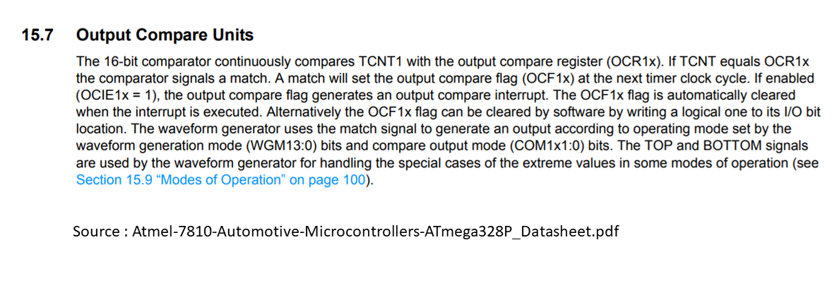
In the datasheet, Output Compare Units is clearly written here. The 16-bit comparator continuously compares T count one (TCNT1) with the output compare register; output compare register A or B. If TCNT equals OCR1x register, the comparator signals a match. A match will set the output compare flag at the next timer clock cycle. If enabled, the output compare flag generates an output compare interrupt. Basically, we have to implement the ISR for output compare interrupt.
You can work with this timer in different modes. In the datasheet, explore the 15.9 section to understand various modes of operation.
Let’s go to 15.9 Modes of Operation. You can drive this timer in normal mode; please read here(Figure 5), so you’ll understand what exactly is a normal mode.
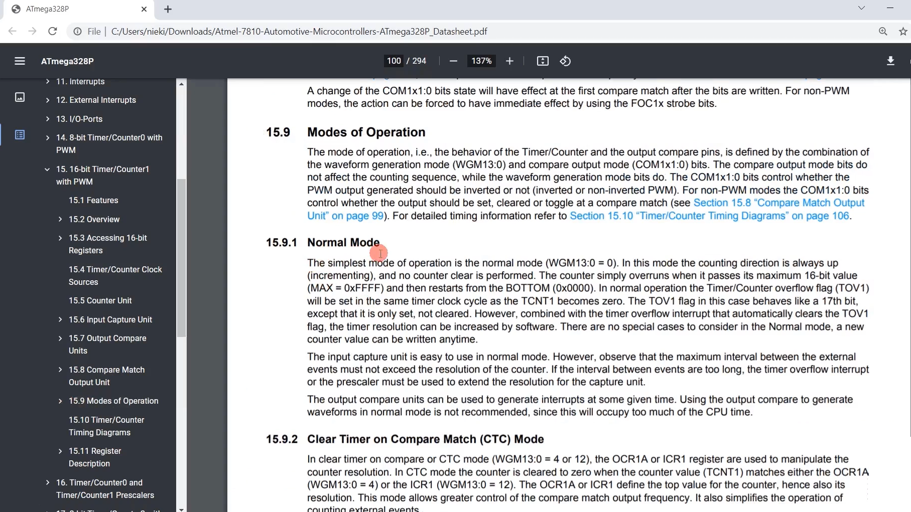
There are various modes. We’ll be driving this timer in CTC mode. That means Clear Timer on Compare Match.
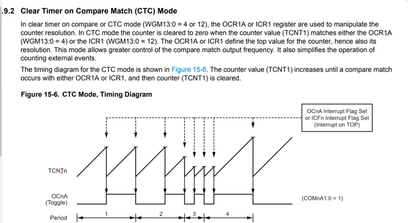
This is how our timer behaves if you use the timer in CTC mode. And this mode can also be used to generate the waveform on some selected pins. But we will not be using that functionality because we don’t want that.
In Figure 6, you can see the meaning of CTC mode. Here they have clearly written.
Now, let’s talk about the clkT1 clock, also called the timer counter clock. This is a clock that is fed to this engine.
Timer/Counter clock (clkT1)
- In Arduino Uno the ATmega328P MCU is clocked by external 16MHz resonator
- fCLK_I/O =16Mhz
- Timer1 count clock (clkT1) = fCLK_I/O / Prescaler
How to control that prescaler?
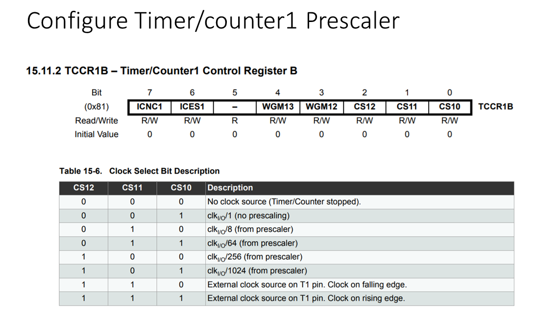
There is a register called TCCR1B, which is Timer/Counter1 Control Register B. And you can see that by using CS12, CS11, and CS10 fields, you can control the prescaling. You can divide the clock by 8, 64, 256, or 1024.
We will use the Prescaler of 256 for this application; then, what happens to our Timer count clock(clkT1)?
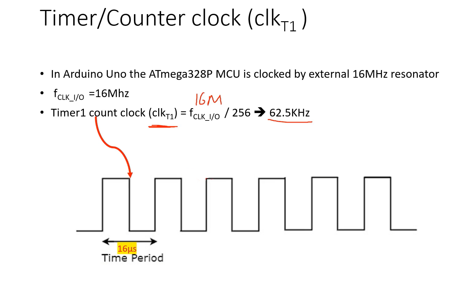
Timer1 count clock(clkT1) = fCLK_I/O (main clock), that is 16MHz divided by 256. That means the timer count clock will become 62.5KHz. So, the timer count clock looks like this with a time period of 16 microseconds. That means the count will happen for every 16 microseconds.
Now, we have to calculate the output compare match values.
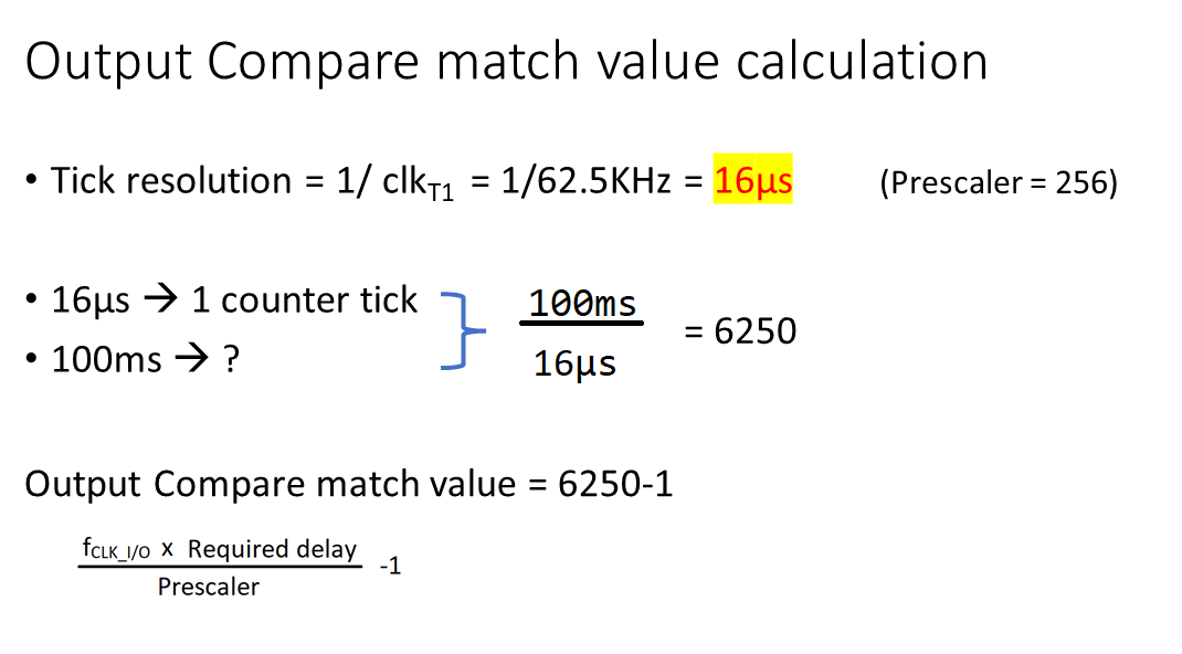
As per our Prescaler, the Prescaler is set to 256; the Tick resolution becomes 16 microseconds. So, for every 16 microseconds, the counter ticks. That means to tick once, it needs 16 microseconds.
Then, how many ticks are required to generate the time base of 100 milliseconds? If you calculate with simple mathematics, we will arrive at this value, which is 6250. That’s why you have to consider output compare match value = 6250-1, and you have to keep this value in the output compare register.
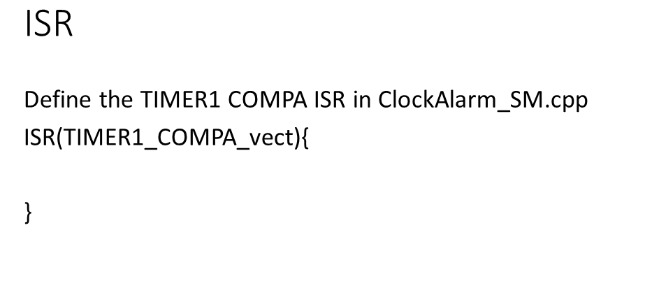
And in the software, we have to define the Timer1 compare ISR. You define that ISR in the ClockAlarm_SM.cpp. You have to use the ISR macro and the vector address. The vector address is this one ‘TIMER1_COMPA_vect’. You have to write exactly like this.
FastBit Embedded Brain Academy Courses
Click here: https://fastbitlab.com/course1

