Exercise: Coding Part 2
In this article, let’s test the master to slave communication application.
- Call the GPIO_ButtonInit() function from the main function, as shown in Figure 1.
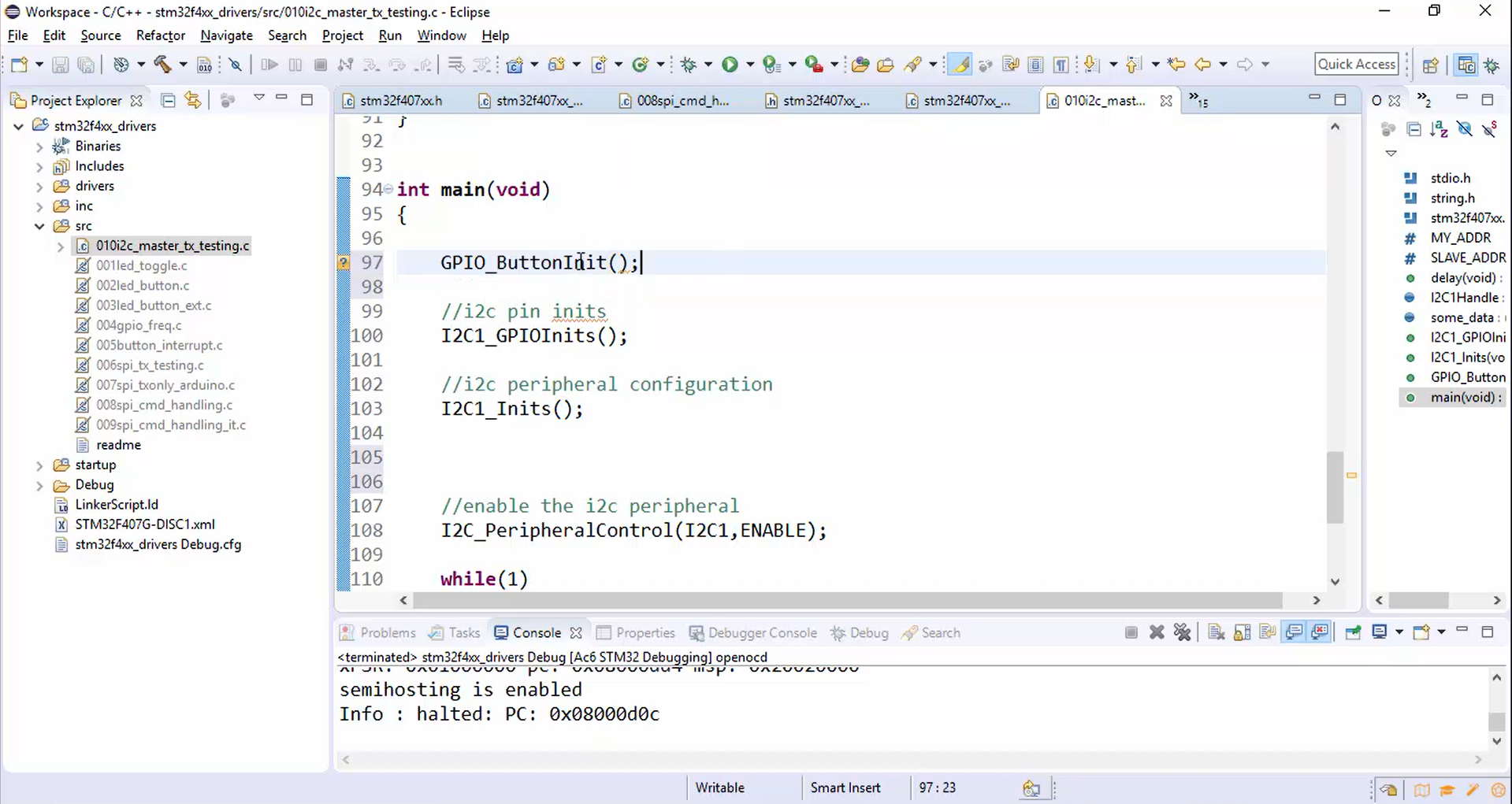
- Compile the code (Figure 2).
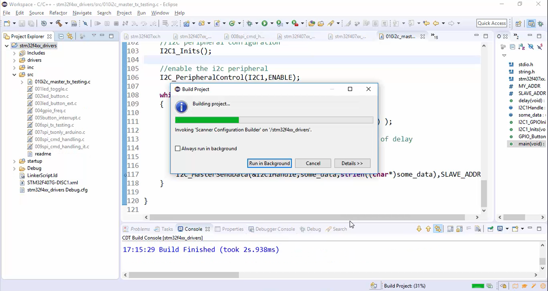
The code is compiled successfully without any errors.
- Download the code into your ST board and reset both ST and Arduino boards.
- Open the logic analyzer software and the serial port of the Arduino (Figure 3).
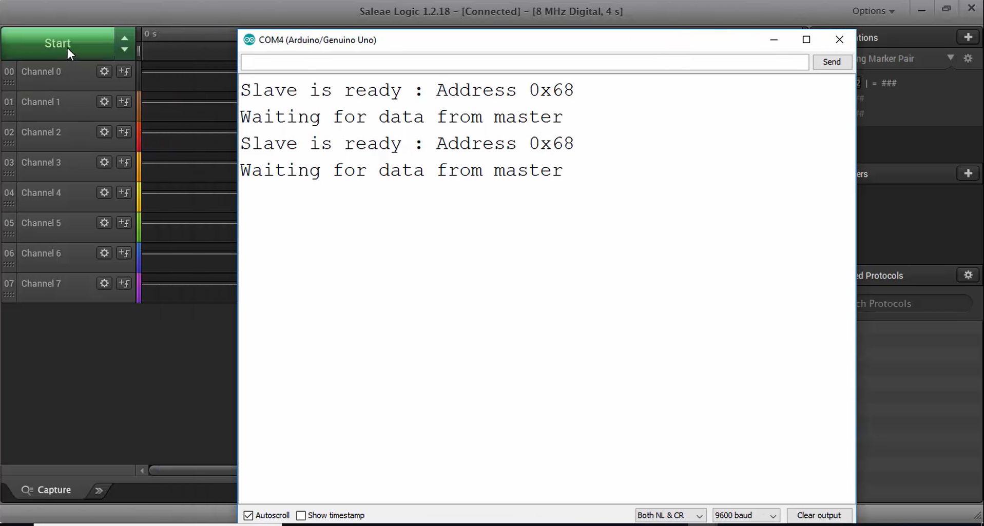
- Press the start button to start capturing the signal and hit the user button on the STM board.
- Open the serial monitor to check whether the slave received the data or not. Observe Figure 4, the slave received the data, and it is displayed on the serial monitor, which is the same as the message we have in our master code.

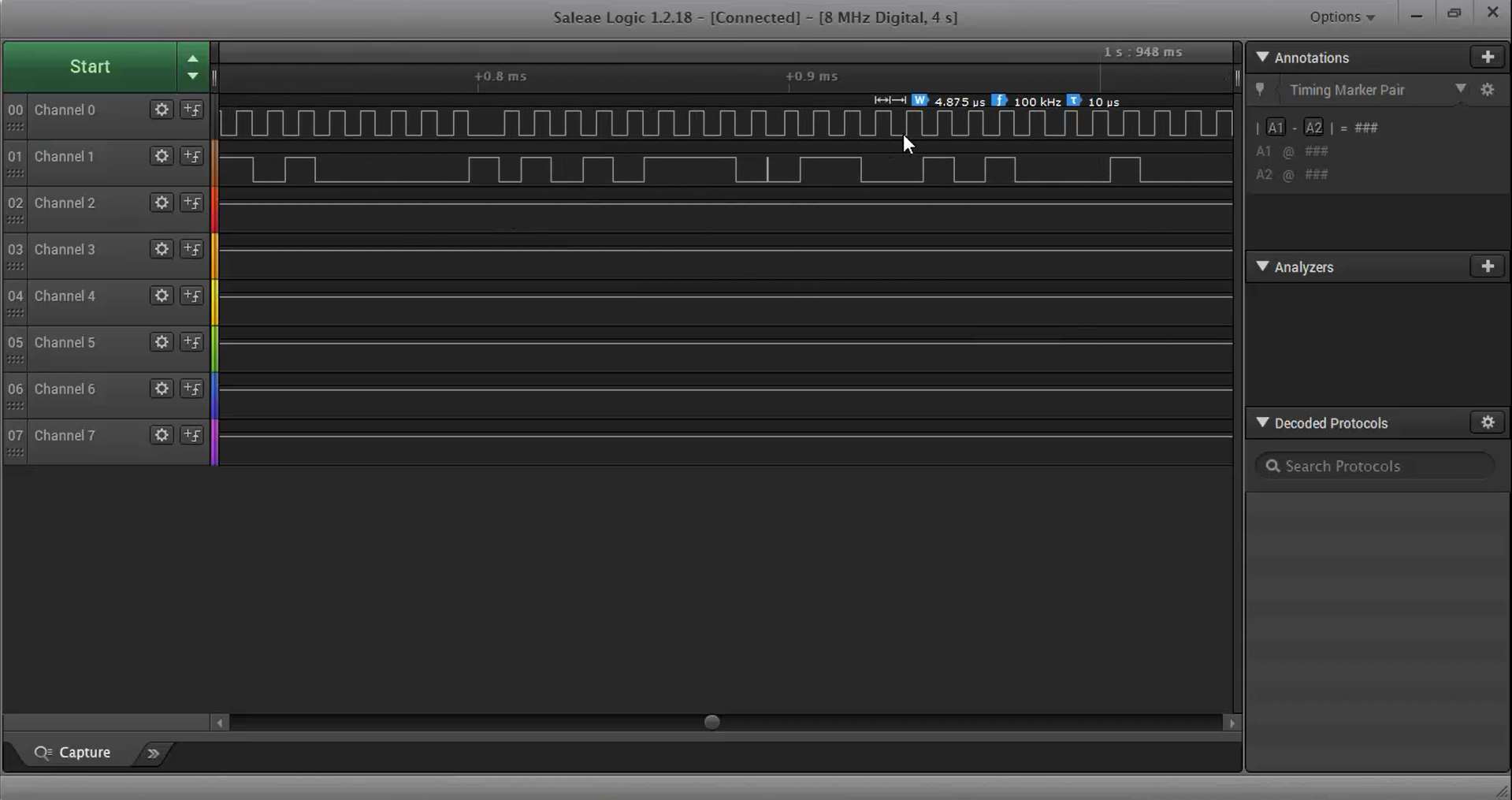
The I2C trace for this exercise is shown in Figure 5, where the first line is SCL, which is 100KHz. Since we are using an internal oscillator, somewhere, the SCL line is 108.97. It has some errors because it depends upon the temperature and various other things. The second line is SDA.
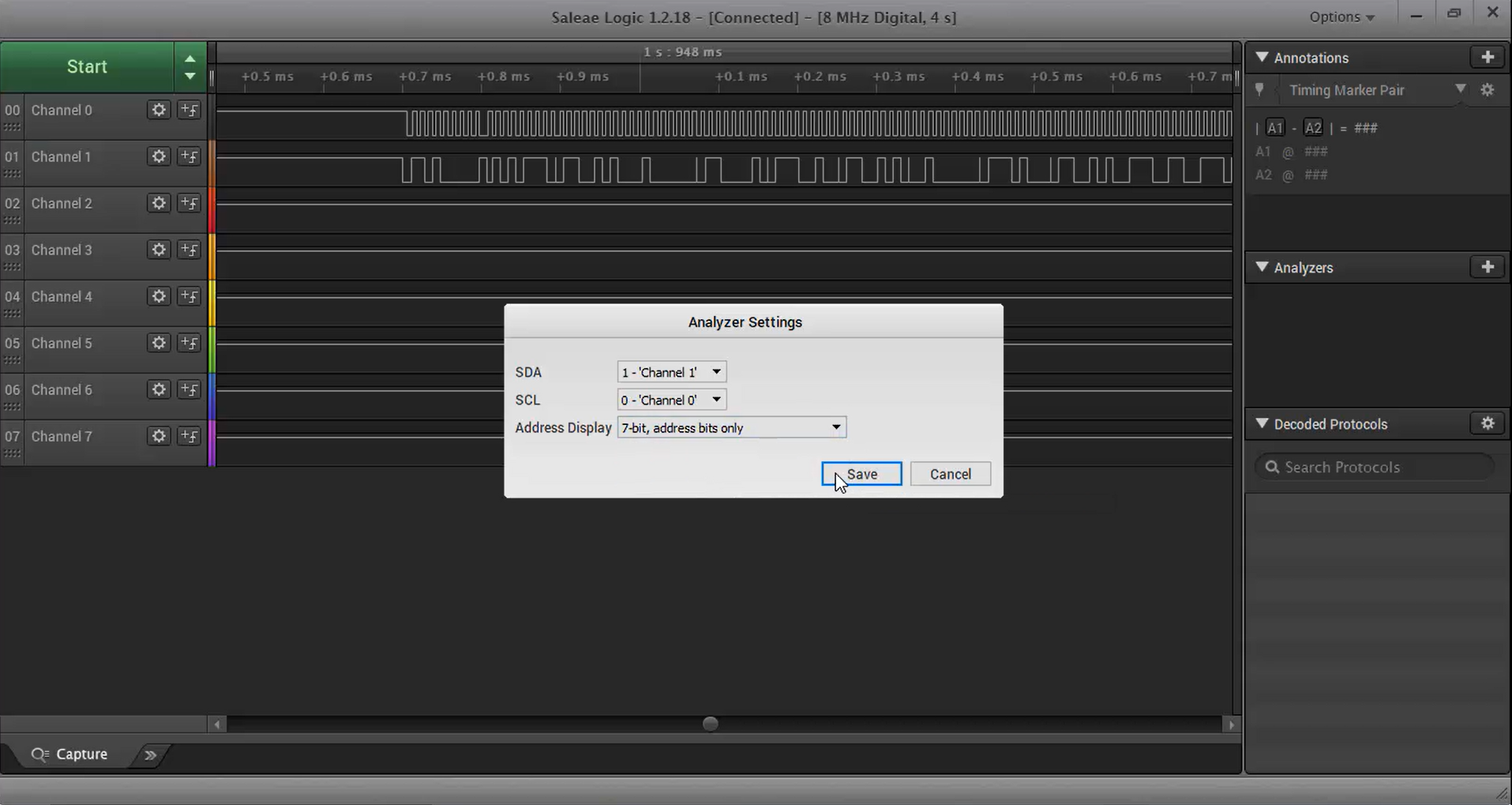
To decode these signals, go to the analyzer, select the channels, and the address display, as shown in Figure 6. Click on save.
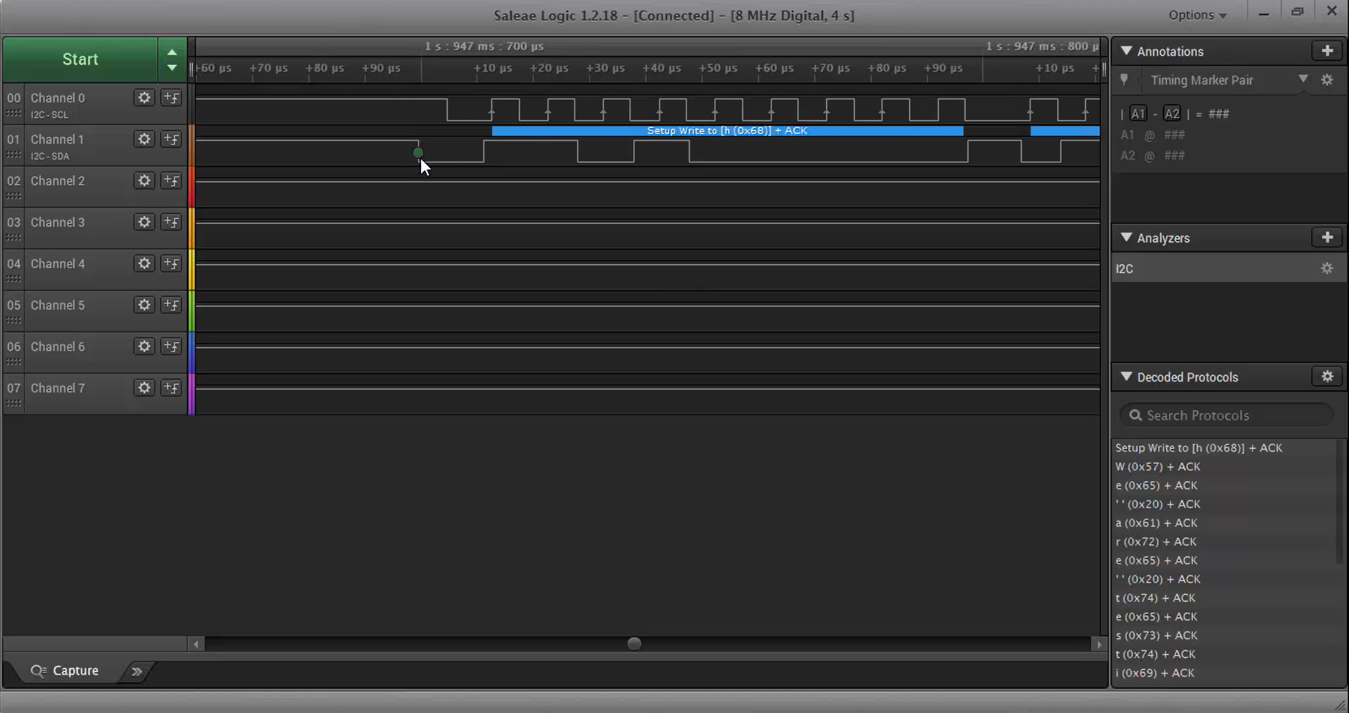
After decoding, you will get a trace shown in Figure 7, where the green circle is a start condition generated by the master, and after that, there is an address phase up to eighth clock cycles. The address is 68, which is a slave address.
After the address phase, the master gets the ACK from the slave. Once the ACK is received, the master writes a very first character (i.e., W) to the slave and repeats this process of sending the data until the last byte (i.e., \n) transfer is complete.
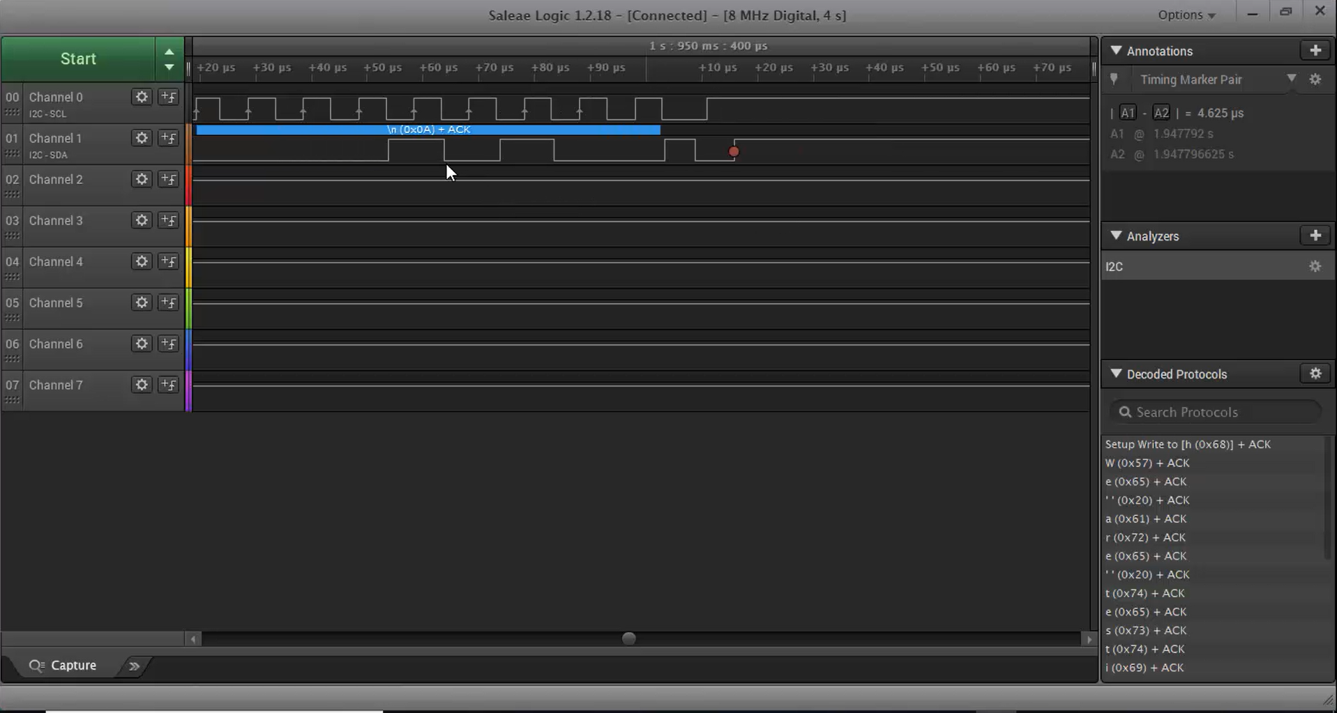
An ACK is received from the slave after the transfer of each byte. Once the data transfer is complete, the stop condition is rised, which is marked with a red circle, as shown in Figure 8.
The master send API is working fine and now try to send more data. It is known that you cannot send more than 32 bytes in single transmission because of Arduino wire library issues. To send more data, execute this API multiple times.
FastBit Embedded Brain Academy Courses,
Click here: https://fastbitlab.com/course1

