Exercise: Coding Part 1
Let’s implement the master and slave communication exercise.
1. Go to the source and create a new file, as shown in Figure 1.
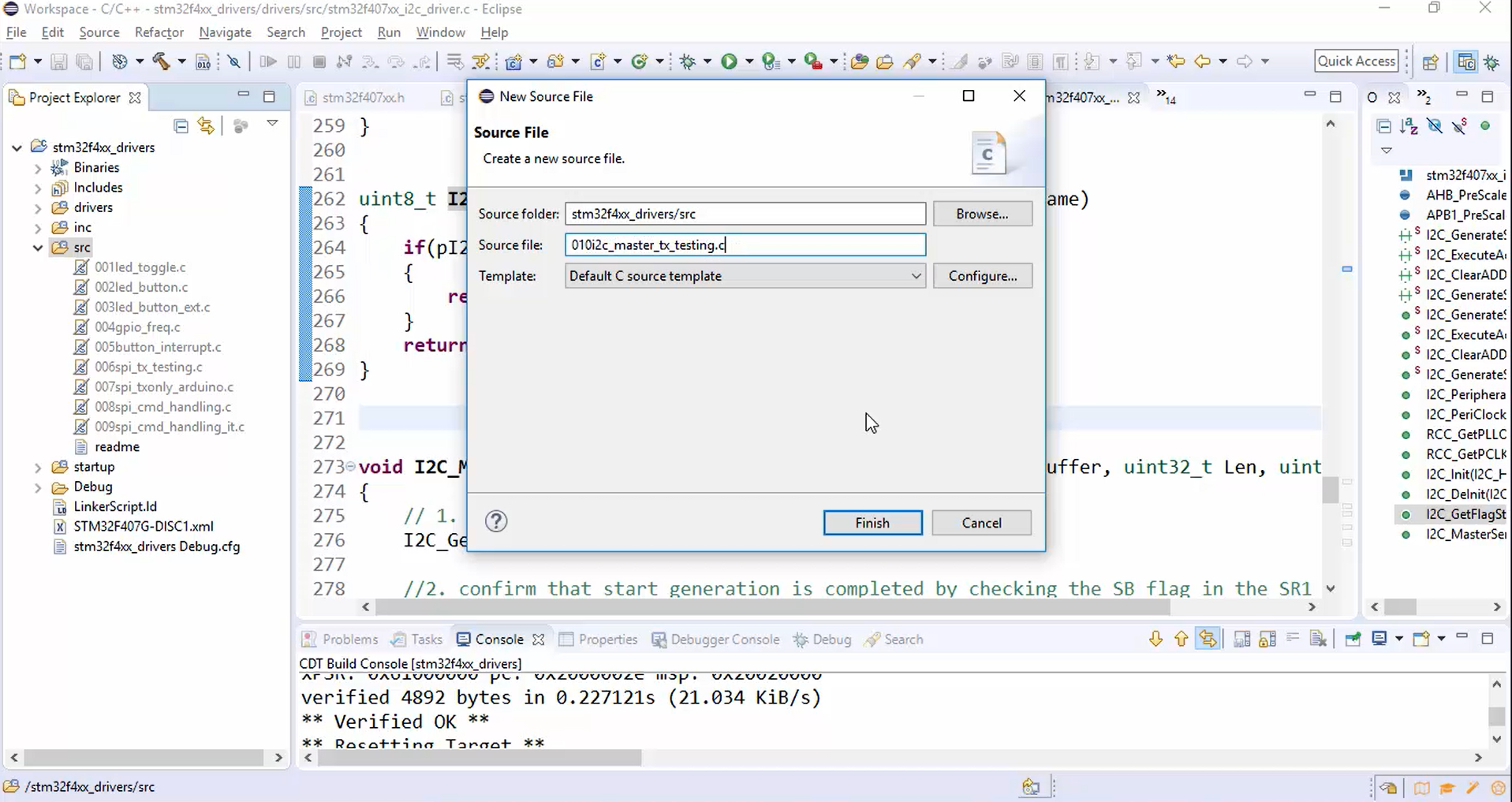
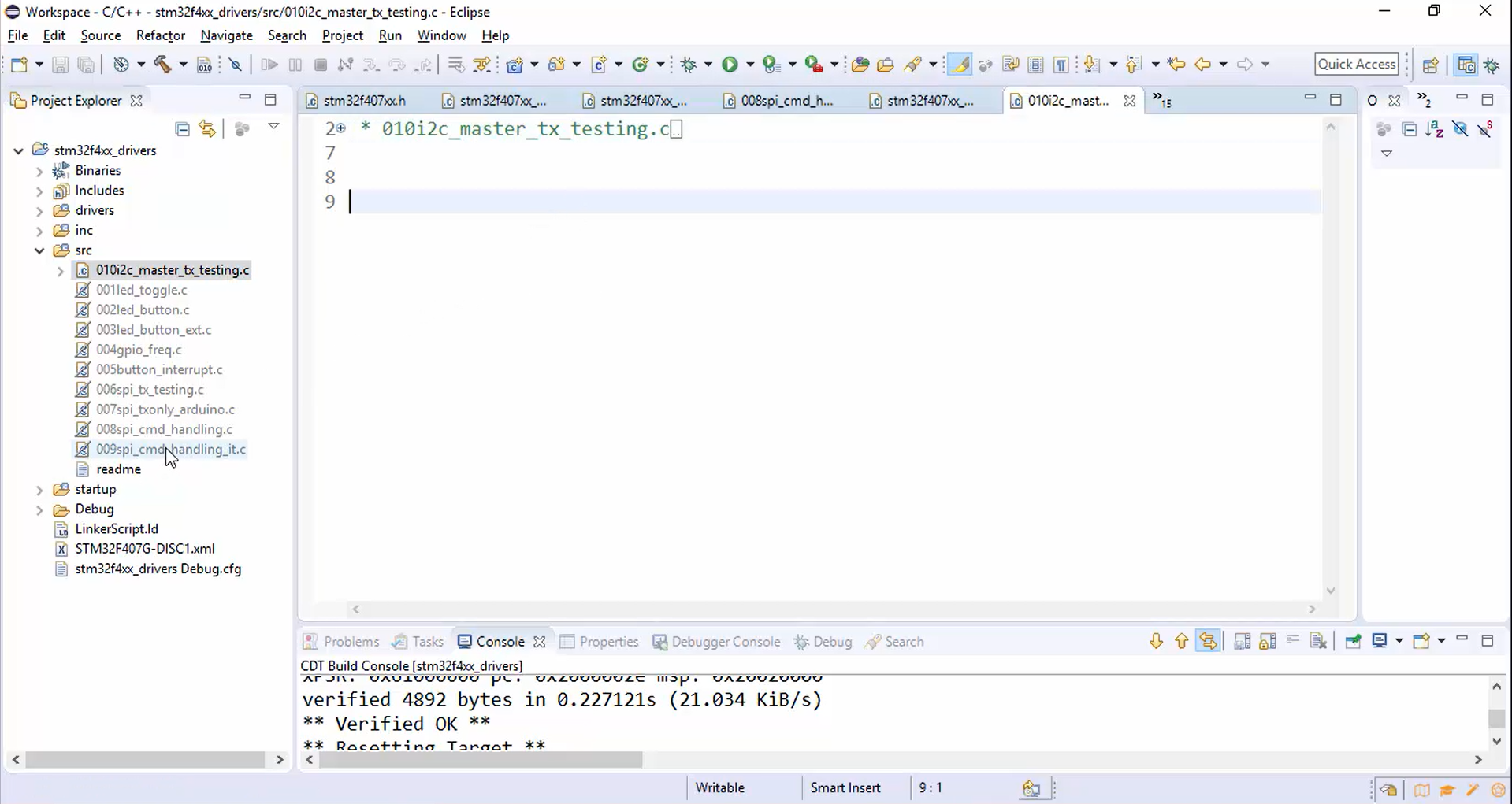
2. After clicking the finish button, a new source file is created, as shown in Figure 2.
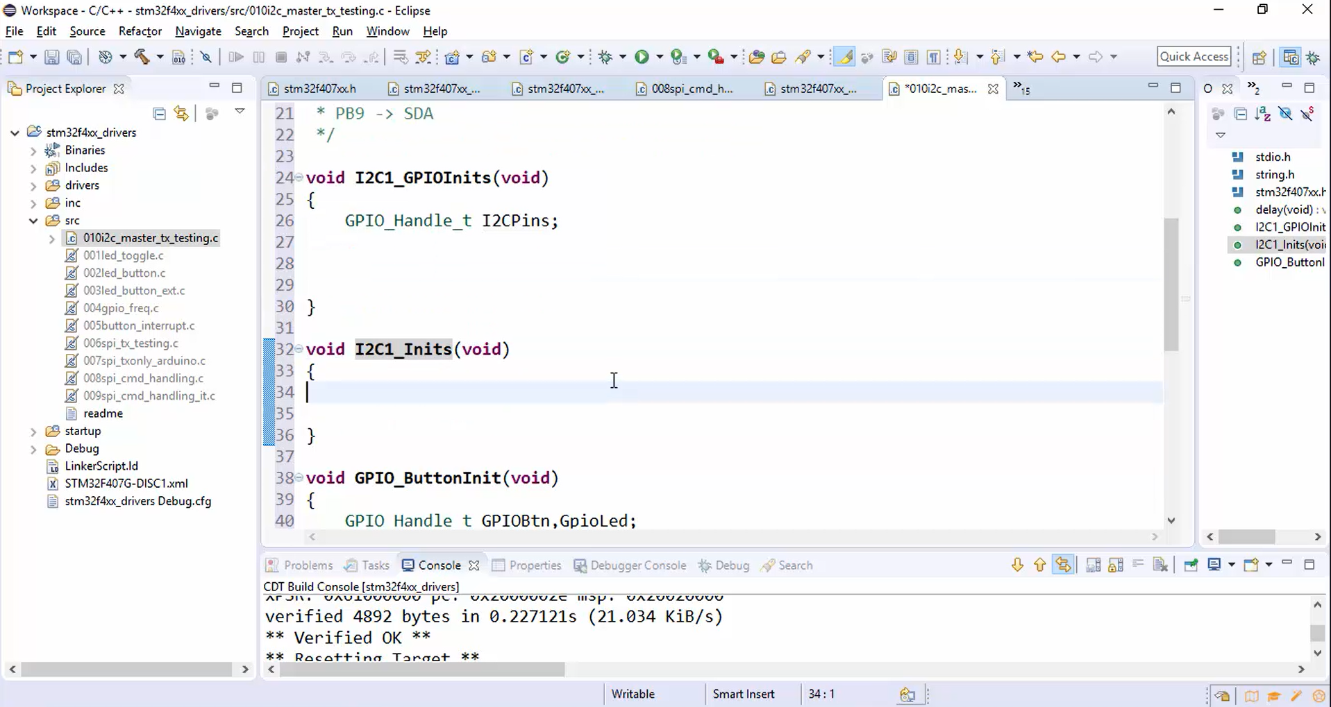
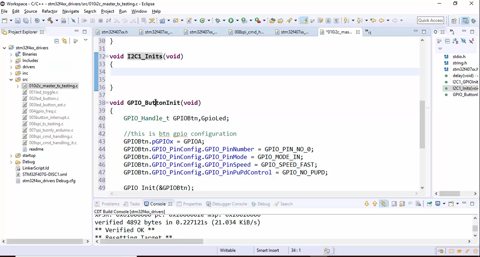
3. Copy some necessary code from the old source file that may be header, delay function, and init functions, as shown in Figures 3.1, 3.2, and 3.3.

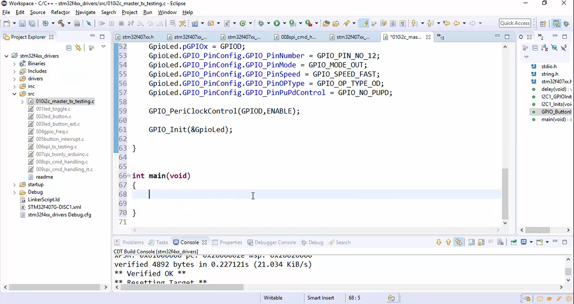
4. Create the main function, as shown in Figure 4.
Code for I2C1_GPIOInits():
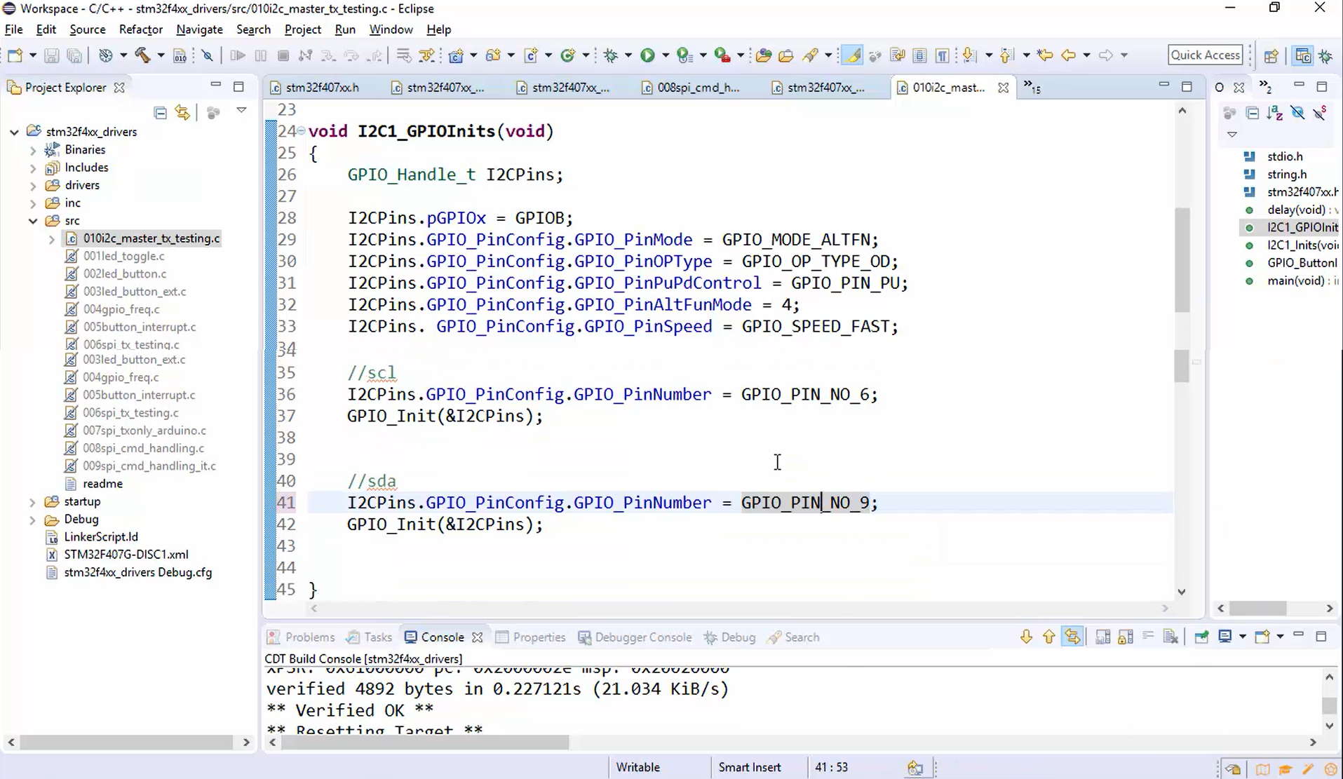
Here the pins are configured to behave as I2C pins (Figure 5).
- Initialize the pin.
- Configure the pin and set the mode to alternate function mode.
- Configure the output type of the pin as the open drain (OD).
- Add the internal pull-up by using the GPIO_PinPuPdControl function since the I2C pins must be in an open drain with the pull-up activated.
- Set the alternate function mode as 4.
- Configure the speed of communication.
- Configure the SCL pin details and initialize it.
- Configure the SDA pin details and initialize it.
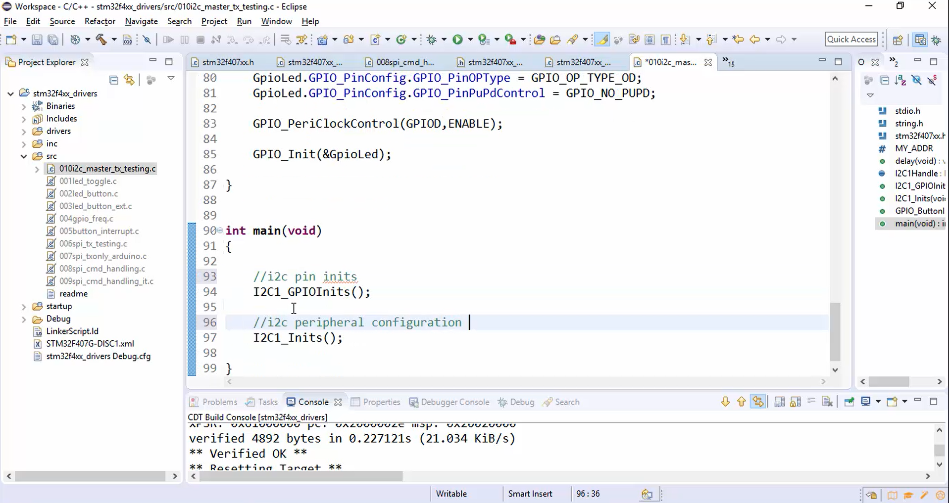
- Call the I2C1_GPIOInits() function from the main, as shown in Figure 8.
Here there is no need to turn on the clock for GPIOB because a driver will do that.
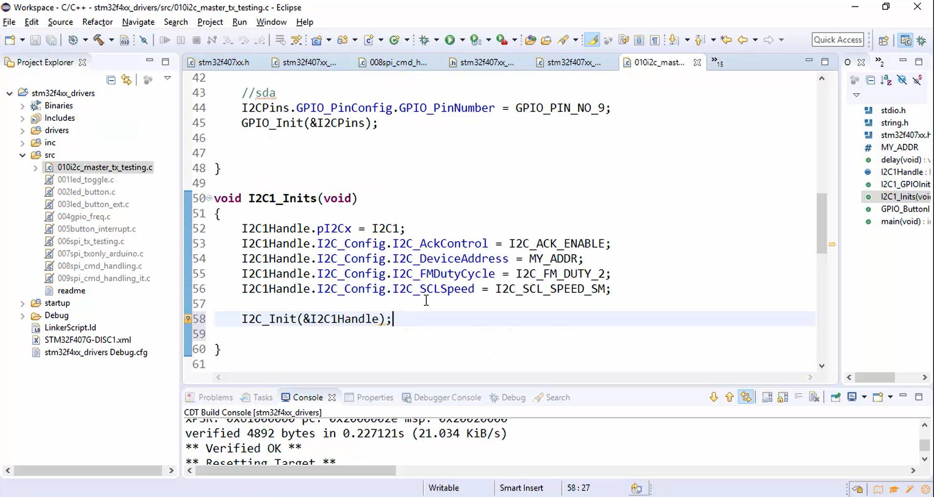
Code for I2C1_Inits(): (Figure 6)
- Create the handle of I2C as a global variable.
- Configure the peripheral base address.
- Enable Ack control.
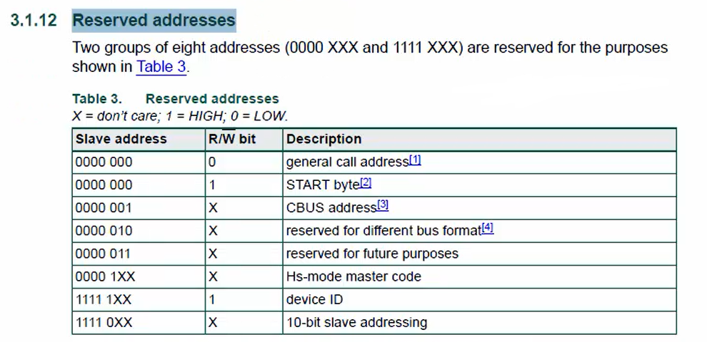
- Assign the device address. It is an optional step since the device is in master mode. The device address is necessary only when the device is in slave mode. Remember to refer to the specification while assigning the device address because some reserved addresses (Figure 7) cannot be used as a device address.
- Configure other fields’ duty cycle as FM_DUTY_2.
- Since we are using the standard mode here, use the speed in Standard mode, which means initialize the SCL speed to 100KHz.
- Call the I2C_Init() and send the address of the handle.
- Call the I2C1_Inits() from the main, as shown in Figure 8.
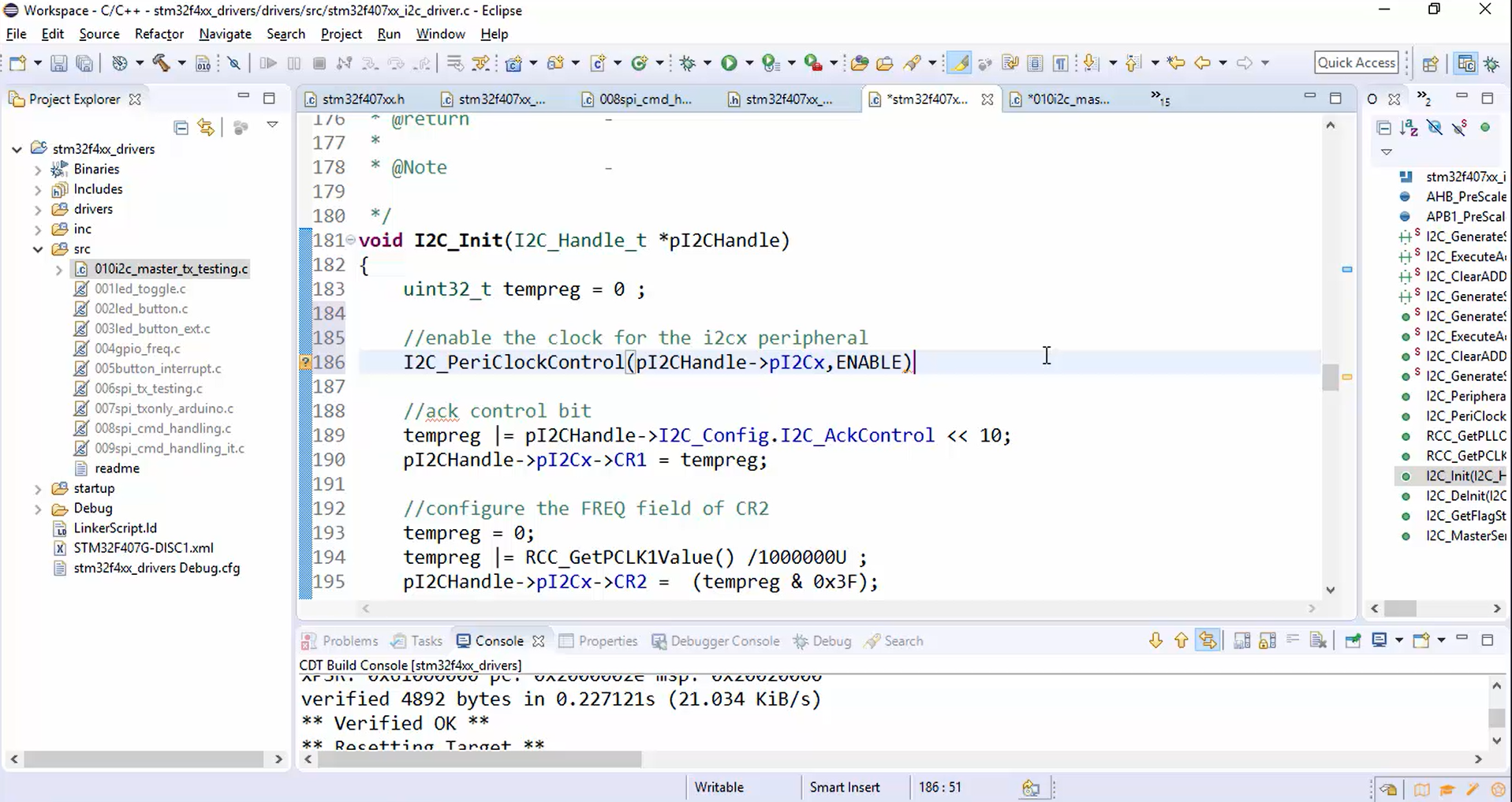
5. Enable the clock for the I2C peripheral in I2C_Init(), as shown in Figure 9.
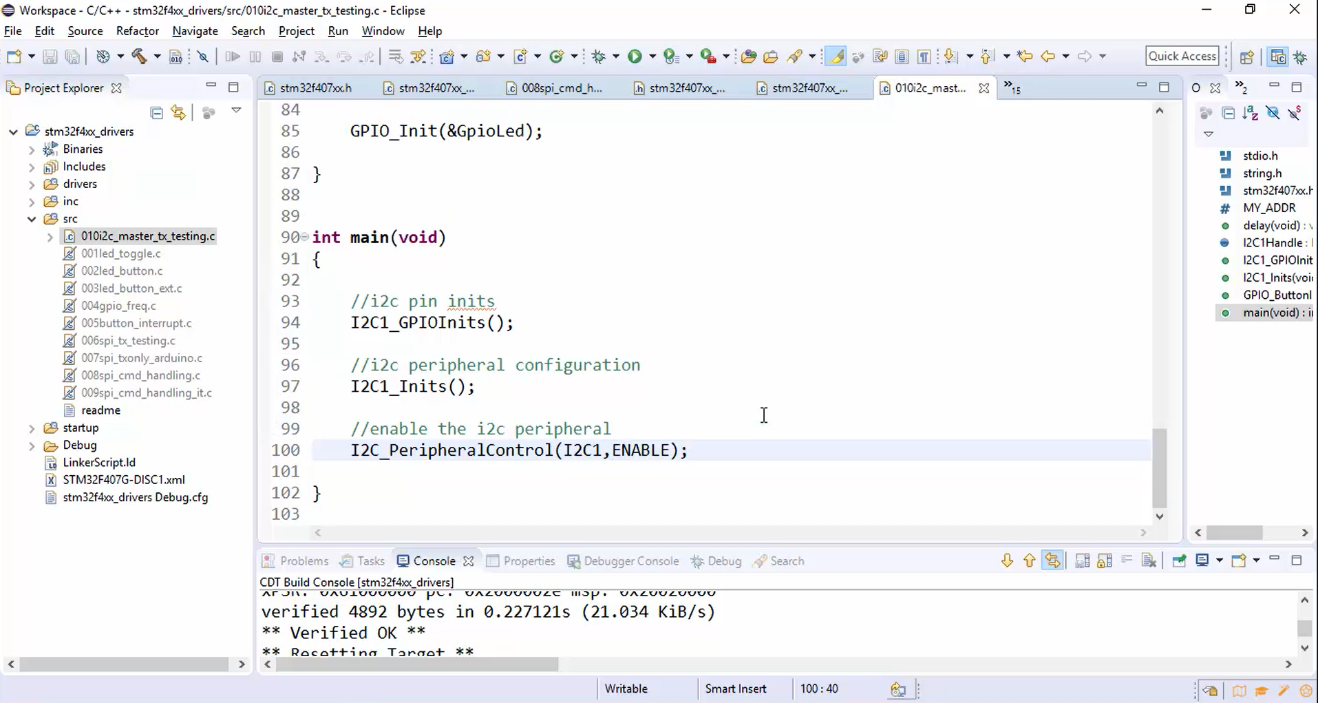
6.Enable the I2C peripheral, as shown in Figure 10.
7. Send the data to the slave:
a. Create some data in the global space. some_data[] = “We are testing I2C master TX\n”.
Note: On the Arduino side, the sketch is written using the Arduino wire library. The wire library has limitations on how many bytes can be transferred or received in single I2C transactions. The limit is 32 bytes. So, don’t send/receive more than 32 bytes in a single I2C transaction. You may split into multiple I2C transactions.
b. Send the data using I2C_MasterSendData(), as shown in Figure 11.
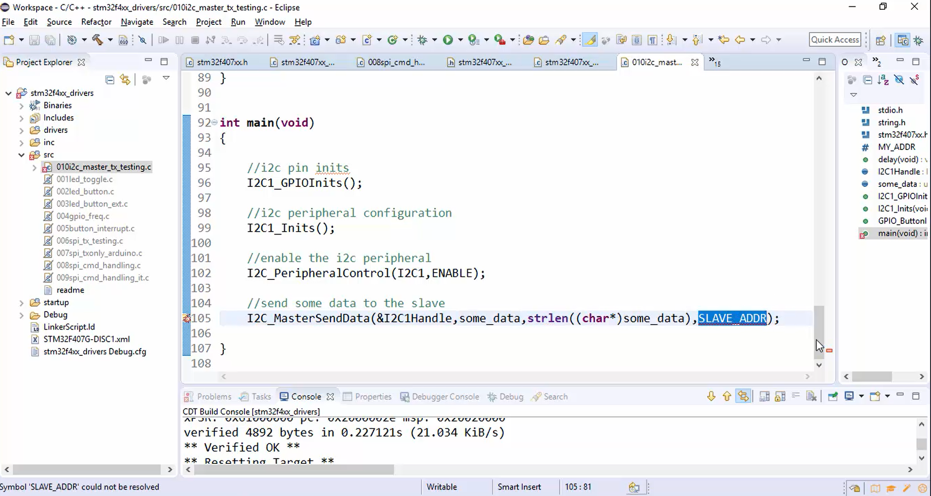
c. Define the slave address: The slave address is nothing but the address of the Arduino board. First, to find out the slave address, open the Arduino sketch, compile it, and then click on the upload button to download your code into the board. After that, go to tools and open the serial monitor, which shows the address of the slave, i.e., 68. Now set the slave address to 0x68.
8. Build the project (Figure 12).
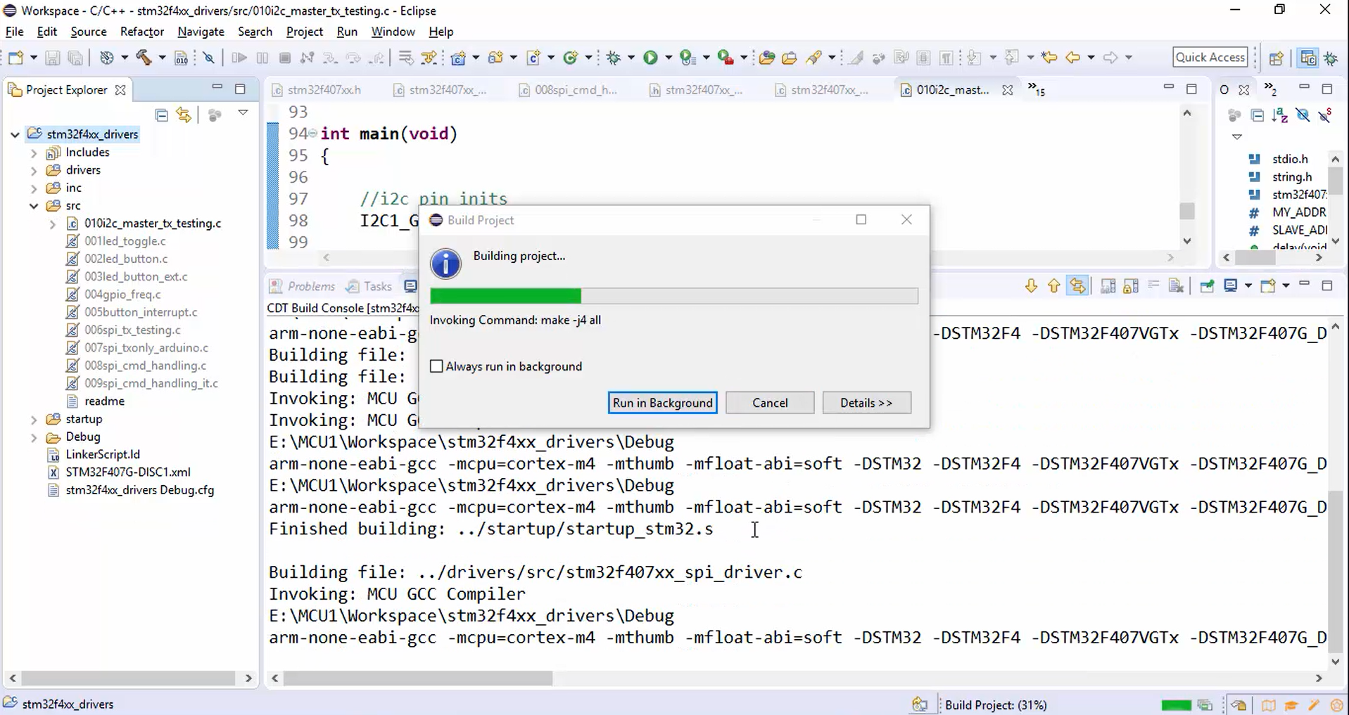
The project is built successfully without any errors and warnings.
9.Wait for a button press, as shown in Figure 13.
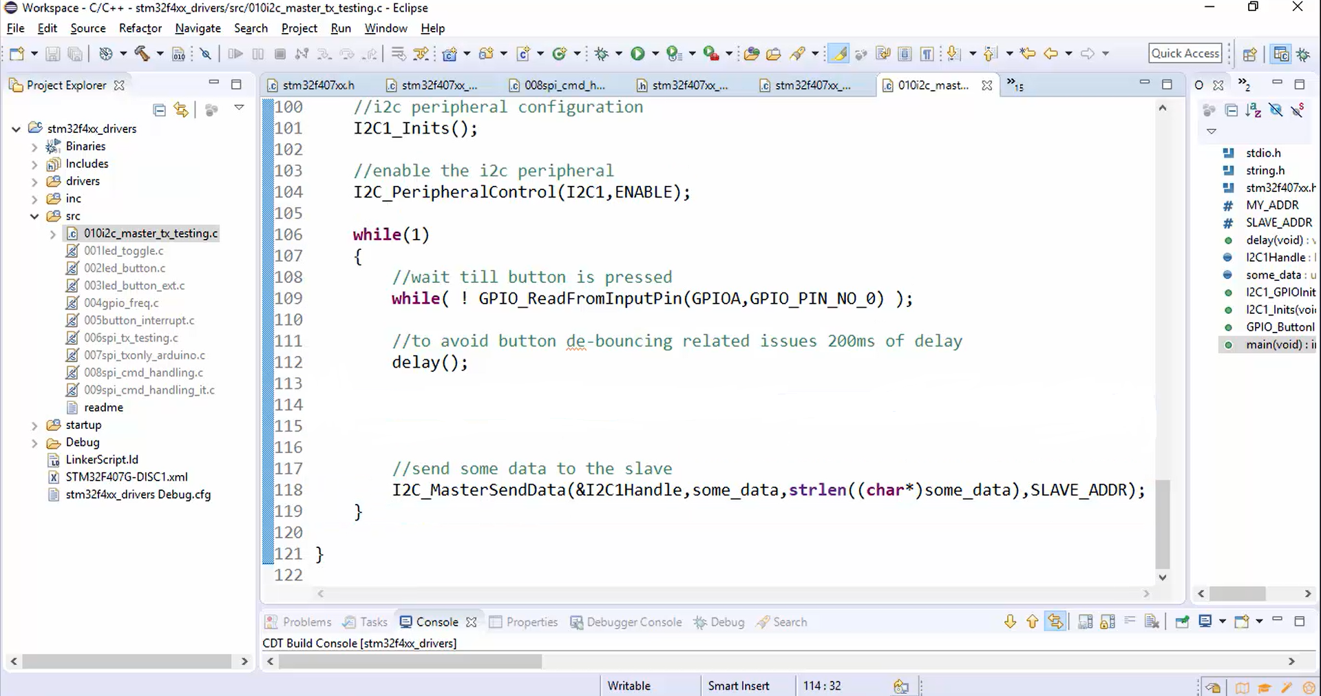
Now compile once again.
In the following article, let’s test the master to slave communication application.
FastBit Embedded Brain Academy Courses,
Click here: https://fastbitlab.com/course1

