Exercise-007 Implementing CLOCK_SETTING state part-2
In the previous article, we completed adding codes for Clock_Setting sub-states.
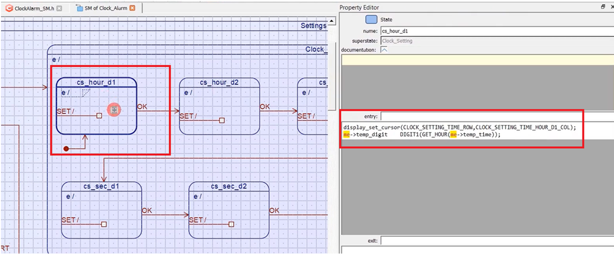
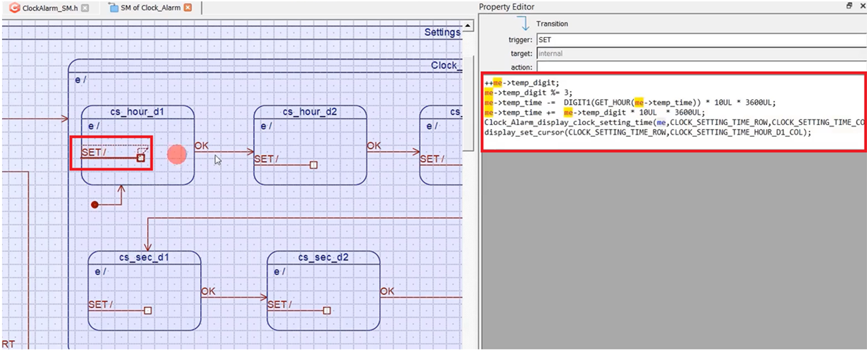
First of all, let me explain from cs_hour_d1. Let me just quickly explain what we did here. Here, cs_hour_d1 is to change the DIGIT1 of the hour field. Whenever we take entry into this state, we just Set the cursor at the CLOCK_SETTING_TIME_HOUR_D1_COL column of the display, and we save the first digit of the hour field of the temporary time—code as shown in Figure 2.
Whenever ‘SET’ signal is received, we just increment the digit; ++me -> temp_digit;
And the DIGIT1 of the hour field can vary between 0, 1, 2. That’s why I do a modulus operation with 3. me-> temp_digit %= 3;
Then, we update this temporary time. I subtract these many seconds and then I update with the new value here
me-> temp_time -= DIGIT1(GET_HOUR(me-> temp_time)) * 10UL * 3600UL;
me-> temp_digit * 10UL * 3600UL;
And then, we update the display here. And we again Set the cursor back to that position.(Figure 3)
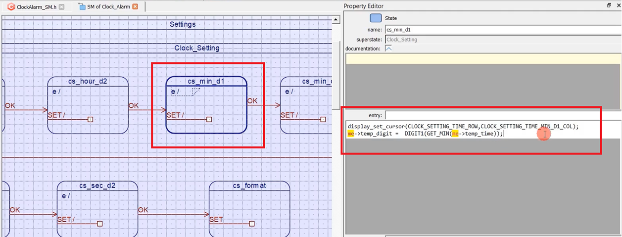
For the cs_min_d1, the same thing. Here, me-> temp_digit = DIGIT1(GET_MIN(me-> temp_time)); temp_digit = DIGIT1 of the minute field of the temporary time.
Set the cursor at this location CLOCK_SETTING_TIME_MIN_D1_COL—clock setting minute field code as shown in Figure 4.
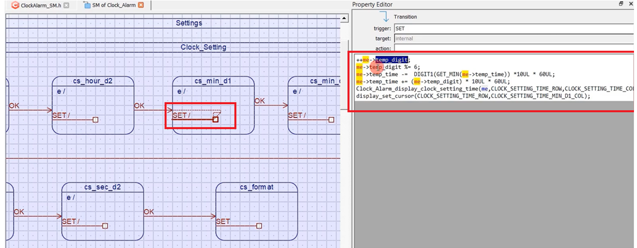
And whenever the SET is received, we increment that digit; the D1 of the minute field can vary between 0 to 5. That’s why I do a modulus with 6 and then subtract DIGIT1 of the get minute. DIGIT1 of the minute field of the temporary time. You must multiply by 10 into 60 because it’s a minute field. 1 minute = 60 seconds. That’s why I multiply by 60. Since it is in 10th place, I have to multiply by 10, and then I compensate for that here with this new value(me->temp_time += (me-> temp_digit) * 10UL * 60UL). And then, we display and set the cursor back to that location (Figure 5).
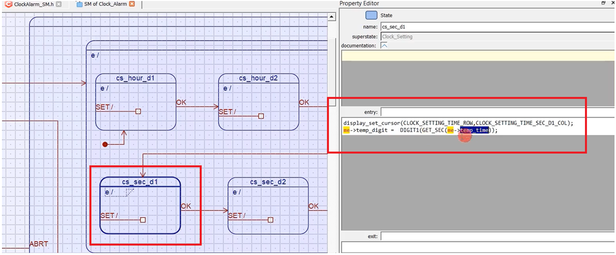
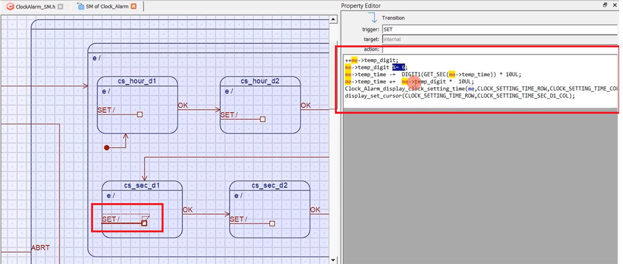
If it is D1 of the second field, the same thing here, DIGIT1 of the second field of the temporary time. The seconds field code is shown in Figure 6.
And whenever the SET is received, we do like this, as shown in Figure 7.
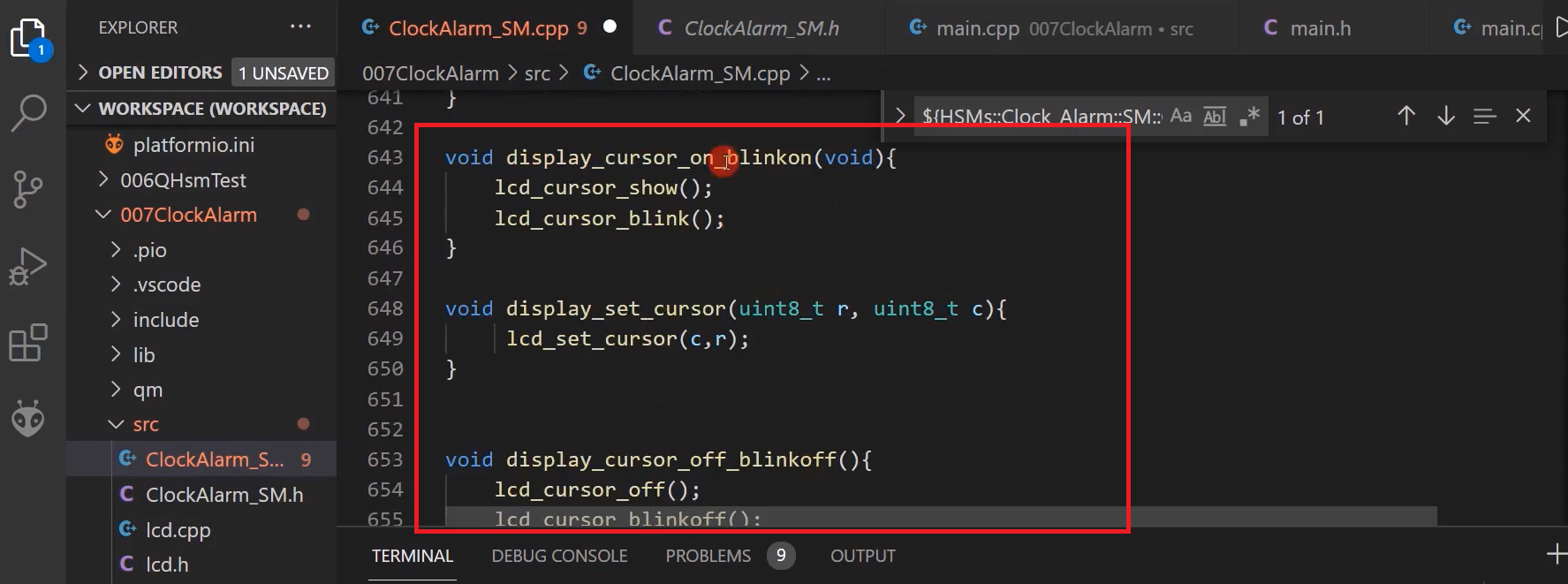
Here we have introduced 3 functions. The first function is ‘display_cursor_on_blinkon’; we must add the definition to our source file. And we also introduced two more functions, display_set_cursor and also this one display_clock_setting_time.
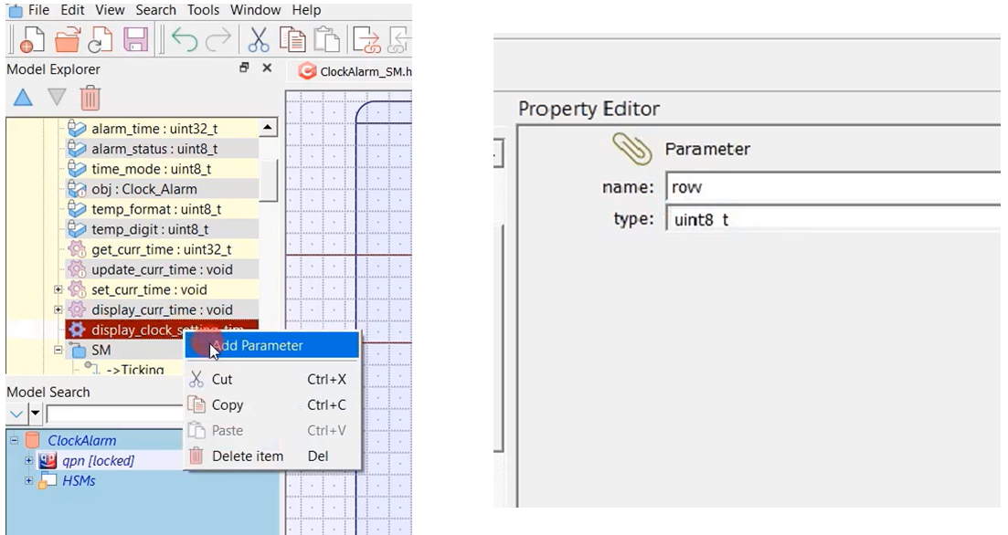
display_clock_setting_time, we added that here as a class operation, but we didn’t add any parameters. It takes rows and columns as parameters. Let’s add that, shown in Figure 8. Name is row, and type is uint8_t. Add another one, the name is col, and the type is uint8_t.
void display_cursor_on_blinkon(){
         lcd_cursor_show();
         lcd_cursor_blink();
}

void display_cursor_off_blinkoff(){
         lcd_cursor_off();
         lcd_cursor_blinkoff();
}

void display_set_cursor(uint8_t r,uint8_t c){
         lcd_set_cursor(c,r);
}
TODO file
Now, let’s go back to our TODO file. display_cursor_on_blink_on(), display_cursor_off_blinkoff(), display_set_cursor(), these are all free operations, just some helper functions. We can straightaway add these functions. Just copy them.
Go to the source file, and at the end, I’m just directly adding this to my ClockAlarm_SM.cpp file because I have selected it as an external file here to add some code. When it is an external file, you can edit that.
And provide the prototypes of these functions.
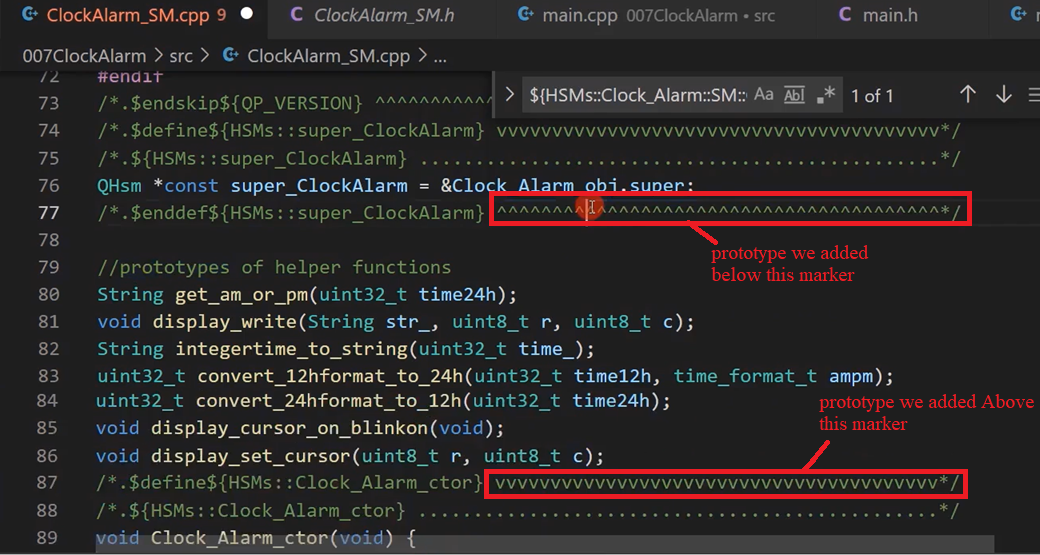
Please note that we added a prototype between the markers, as shown in Figure 10.
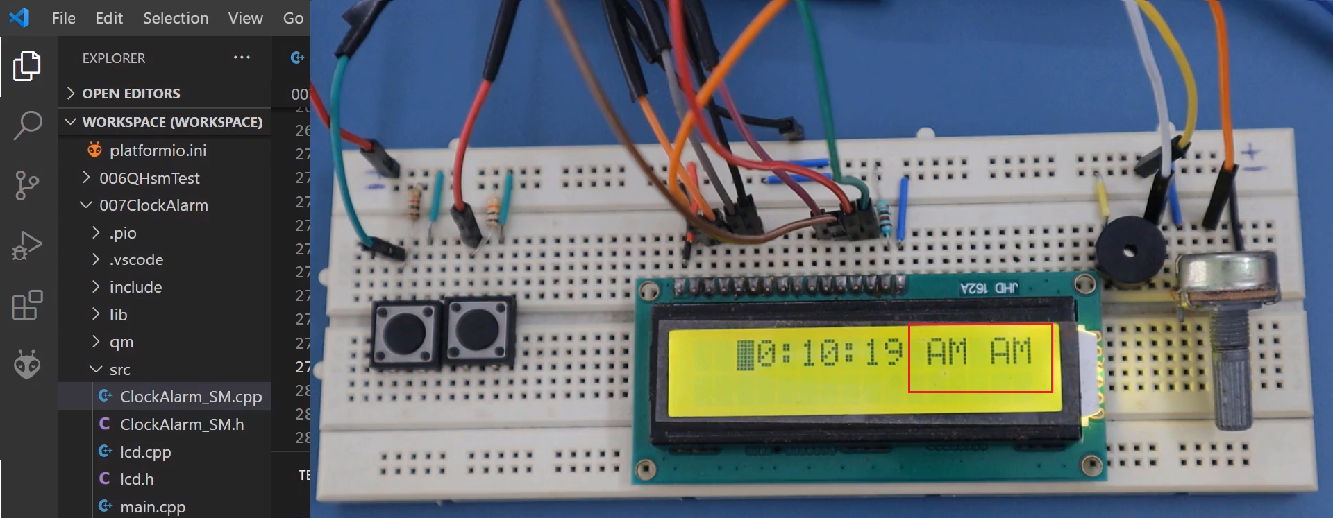
Let’s test this on the target. Let’s compile this and download it. Let’s press the ‘SET’ button; you can see that(Figure 11) there is some problem. There is some cleanup issue. This you need to take care.
For this, I think we have to add some cleanup actions or exit actions. Let’s go back to the model. And in Ticking state, you add an exit action to clear the display. Let’s add that.
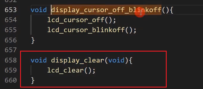
Go back to the code. At the end, add void display_clear. Here, I just called the lcd_display or lcd_clear function. And also, add the prototype void display_clear(void).
And let’s call this function from the model here.
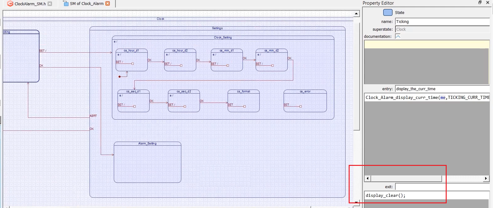
Let’s define an exit action for Ticking state, display_clear(); we’ll also define one exit action for Setting state. Whenever the Settings superstate is exited, the display must be cleared. I’ll put that code display_clear.
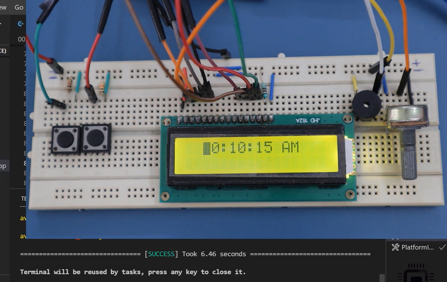
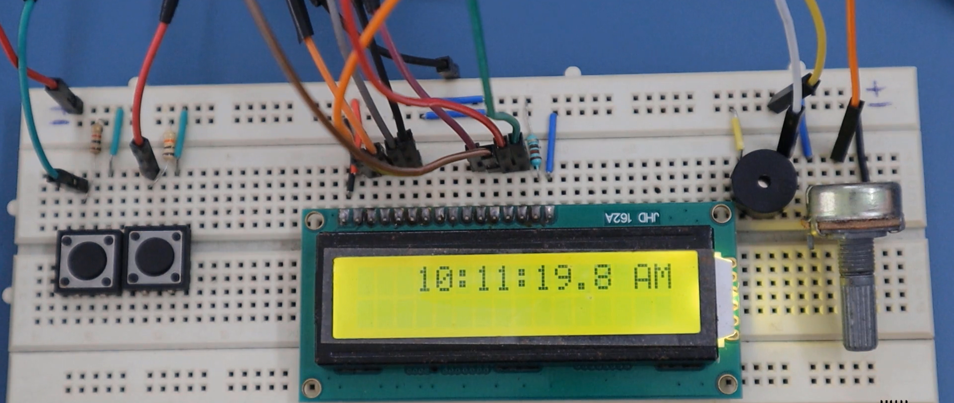
Let’s generate the code. I’m reuploading this. Let’s check. I’m going to press the SET button. Now it is fine, as shown in Figure 14.
And now I can keep pressing this ‘SET’ button to change the digits. The D1 of the hour field moves around 0, 1, and 2. After 2, it becomes 0. Then ‘OK’ goes to the following field. Here, you can change upto 9; it goes back to 0 and then moves to the minute field. After the minute field, then it moves to the second field.
You can Abort this operation. Whenever it is Abort it, as you can see in the diagram, there is just a transition back to the ticking state. Let me Abort this.(Figure 15)
You can see that it is Aborted. But, the real current time is not disturbed because the interrupt service code maintains it. Complete up to here and if you have the hardware, test it.
And in the upcoming article, we will take care of how to handle cs_format and also how to handle the cs_error because the user may enter some wrong values. That’s why we have to flag the error in case the user entries are not valid.
FastBit Embedded Brain Academy Courses
Click here: https://fastbitlab.com/course1