GPIO Output data register and summary of various modes discussed

GPIO Output data register is used to control the I/O state of the I/O pins.
Here only16-bits are used in this register. So, 16 to 31 are reserved, and the 0th-bit position will control the I/O pin 0.
If you write one means corresponding I/O pin as high and if you write 0 means corresponding I/O pin as is low.
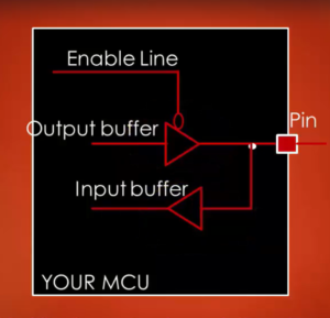
So, these bits can be read and written by software. By taking various modes and Pull-up/Pull-down registers combinations below configuration obtained for a GPIO pin:
- Input floating.
- Input Pull-up/Pull-down.
- Analog.
- Open drain with Pull-up/Pull-down.
- Push-pull with Pull-up/Pull-down.
- Alternate function open drain with Pull-up/Pull-down.
- Alternate function push-pull with Pull-up/Pull-down.
In the following article, let’s see Alternate functionality setting of GPIO pin with example.
FastBit Embedded Brain Academy Courses,
Click here: https://fastbitlab.com/course1


