Introduction to SPI Bus
The Serial Peripheral Interface (SPI) is a synchronous serial communication interface specification used for short-distance communication, primarily in embedded systems.
In this introduction, we delve into SPI’s fundamental components, functions, and its role in connecting devices efficiently.
The SPI interface can be used to communicate with external devices using the SPI protocol. Typical applications include Secure Digital cards and liquid crystal displays.
SPI is one of the protocols which is used to communicate with the one master and couple of slave devices in the embedded world.

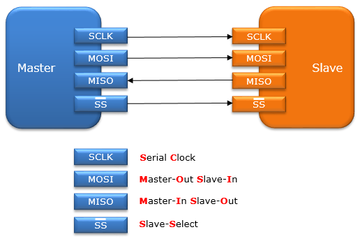
From Figure 1. Let’s say there is one master device and one slave device.
The master is a microcontroller board. The slave may be anything it can be a sensor, and it can be an EPROM chip, it can be an SD card, it can be a display or wireless connectivity chips such as WiFi or Bluetooth controlled. If the master wants to communicate with the slave, that means the master wants to send data to the slave or retrieve data from the slave. A specific protocol is defined, and SPI is one among them.
There are various protocols like CAN protocol, I2C protocol, Ethernet, USB, RS232, RS485, and SPI is one among them. SPI bus is a collection of a couple of pins.
SPI bus which allows communication between one master device and one or more slave device. SPI is a protocol used for serial data communication between one master and a couple of slave devices in an embedded world.
The 4 I/O pins are dedicated to SPI communication with the external devices. Typically, SPI uses 4 or more pins.
Essential SPI Pins: Enabling Communication
SPI’s core communication revolves around four key pins:
SCLK: Serial Clock (output from master).
When the master wants to communicate with the slave, the data which are there on MOSI or MISO pin will synchronize with the clock. In the SPI protocol, the master is the one that produces the clock. Hence SPI is called synchronous serial communication protocol. The slave will only receive the clock, so the slave has no control over the serial clock, which is produced by the master. So, without this serial clock, SPI communication is not at all possible.
MOSI: Master Output Slave Input, or Master Out Slave In (data output from master).
MOSI is a data pin. This pin is used to transmit data in the master mode and receive data in the slave mode. So, as the name suggests, whenever the master sends data, that data will be collected over the MOSI pin by the slave. Thus, the MOSI pin is used to send data from the master side, and the slave will receive it.
MISO: Master Input Slave Output, or Master In Slave Out (data output from slave).
MISO is a data pin. This pin is used to transmit data in slave mode and receive data in master mode. So, as the name suggests, whenever the slave sends data, that data will be collected over the MISO pin by the master. Thus, the MISO pin is used to send data from the slave side, and the master will receive it.
SS: Slave Select (often active low, the output from master).
Depending on the SPI and slave select setting, the SS pin used to select an individual slave device for communication. When there is one master and one slave device, then the SS pin is not required. This slave select pin will make sense only when the master is communicating with the different slaves. So, the master can select the slave to which the master wants to convey. For choosing the slave, the SS pin dedicated. So, that’s why the SS pin is called a slave select or slave control.
In the subsequent article, let’s see SPI comparison with other protocols.
We will explore SPI further and provide a comparative analysis with other communication protocols, shedding light on its unique strengths and applications in the embedded world.


