Keypad key read code implementation
In this article, let’s code for the keypad exercise.
Here I have a new project, the 011keypad, and here I have all peripheral register addresses definition, as shown below.
int main(void)
{
//peripheral register addresses
uint32_t volatile *const pGPIODModeReg  = (uint32_t*)(0x40020C00);
uint32_t volatile *const pInPutDataReg  = (uint32_t*)(0x40020C00+0x10);
uint32_t volatile *const pOutPutDataReg = (uint32_t*)(0x40020C00+0x14);
uint32_t volatile *const pClockCtrlReg  = (uint32_t*)(0x40023800+0x30);
uint32_t volatile *const pPullupDownReg = (uint32_t*)(0x40020C00 + 0x0C);

//1.Enable the peripheral clock of GPIOD peripheral
I have created a couple of pointer variables. The pointer for pull up/pull down register is the new one. And since these are memory-mapped register access, so I have made data as volatile.
Keep all row GPIOs in OUTPUT Mode and column GPIOs in INPUT Mode
//1.Enable the peripheral clock of GPIOD peripheral
*pClockCtrlReg |= ( 1 << 3);


// 2.configure PD0,PD1,PD2,PD3 as output (rows)
*pGPIODModeReg &= ~(0xFF); //clear
*pGPIODModeReg |= 0x55; //set


// 3. configure PD8 , PD9, PD10, PD11 as input (columns)
*pGPIODModeReg &= ~(0xFF << 16);

// 4.Enable internal pull-up resistors for PD8 PD9 PD10 PD11
*pPullupDownReg &= ~(0xFF << 16);
*pPullupDownReg |= (0x55 << 16);
- The first step is to enable the peripheral clock for GPIOD peripheral. For that, we have to refer to the clock register.
*pClockCtrlReg |= (1 << 3);
- The next one is configure PD0, PD1, PD2, PD3 as output. These are our rows.
Now, let’s refer to the mode register.
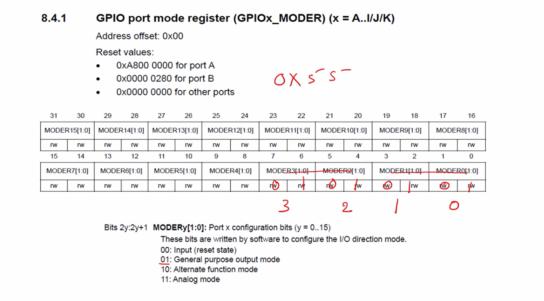
Here MODER0 is PD0, MODER1 is PD1, MODER2 is PD2, MODER3 is PD3. We have to keep all these 01. MODER0 and MODER1 are 5 and MODER2 and MODER3 are 5. This value turns out to be 0x55. So, we have to program 0x55.
We refer to the ModeReg.
*pGPIODModeReg |= 0x55; // This is set
Before that, you can also clear those fields. So, it’s better if we clear those fields first.
*pGPIODModeReg &= ~(0xFF); // This is clear
- After that configure PD8, PD9, PD10, PD11 as inputs( columns).
For that, you have to clear all those bits.
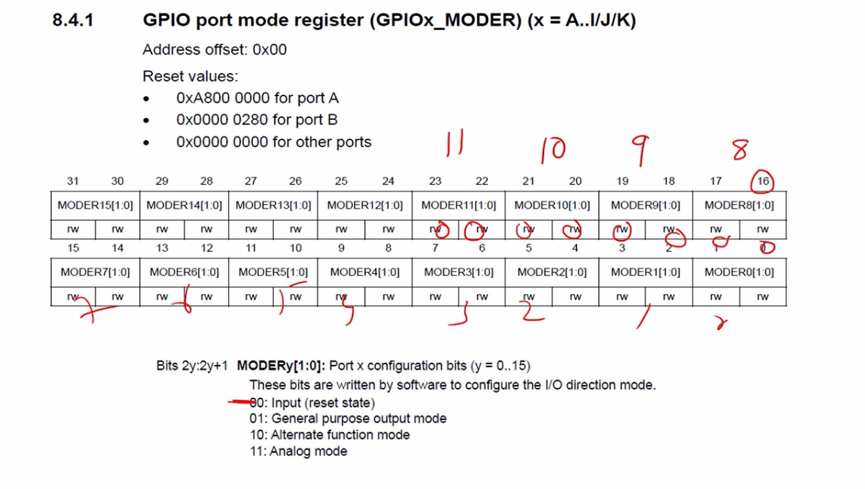
PD8 starts from MODER8. MODER9 is PD9, MODER10 is PD10, MODER11 is PD11. So, all these should be zeros. That is the input mode. That means you have to clear 8 bits from the 16th-bit position onwards.
In the mode register, we are going to clear 8 consecutive bit positions, which appear 16th-bit position onwards. That’s why let’s use ~(0xFF << 16). Why 16? Because the bit position for the 8th pin is at the 16th.
*pGPIODModeReg &= ~(0xFF << 16);
4. Enable internal pull-up resistors for PD8, PD9, PD10, and PD11.
Let’s refer to the GPIO port pull-up/pull-down register.
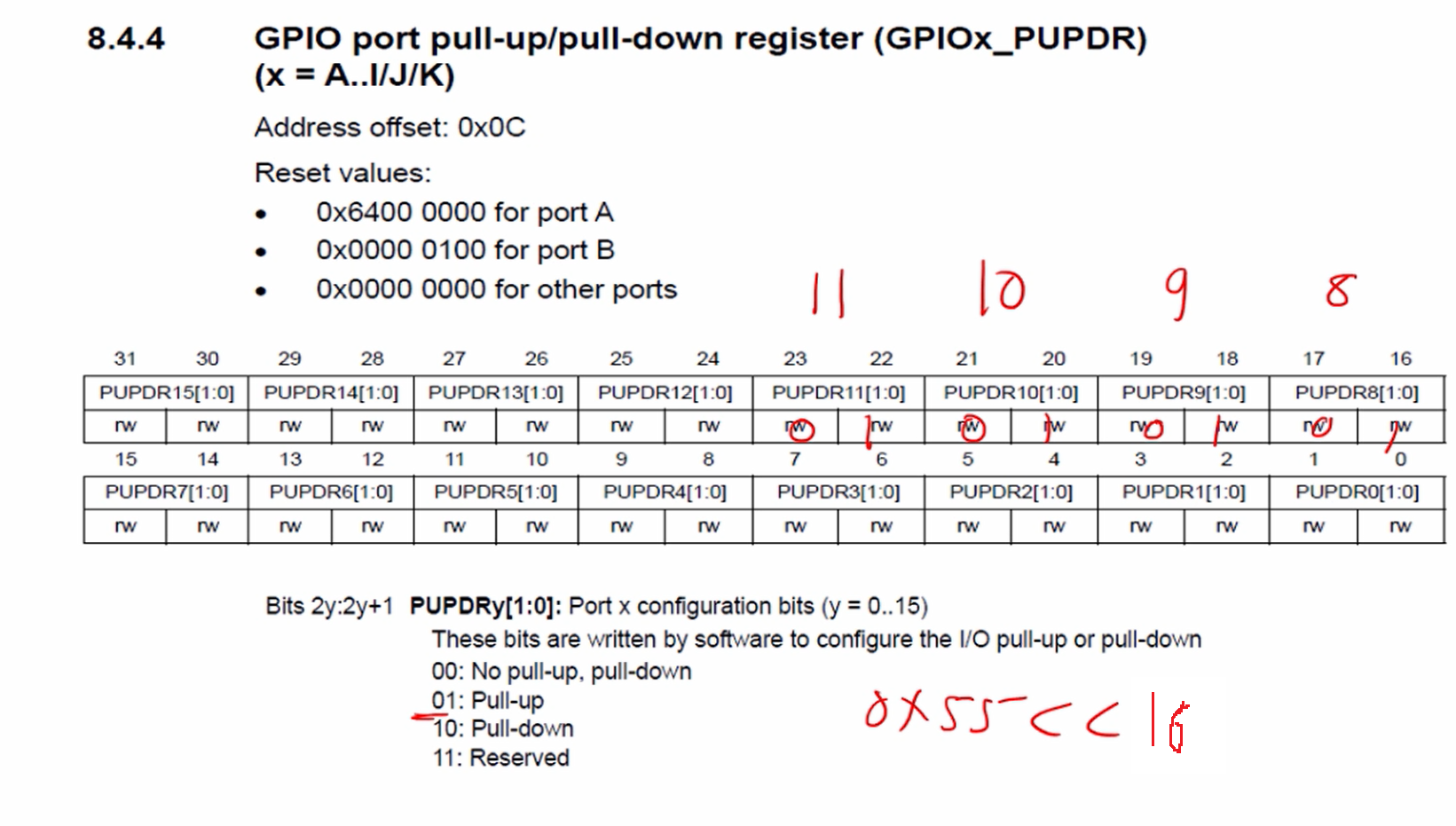
PD8 starts from PUPDR8, PUPDR9 is PD9, PUPDR10 is PD10, PUPDR11 is PD11. And it has to be pull up, so 01. So, I had to keep all these 01 here. This happens to be 0x55, but shifted by 16.
Let’s start with a pull-up/pull-down register.
First, let’s clear those bit positions before setting.
*pPullupDownReg &= ~(0xFF << 16); // Clear
*pPullupDownReg |= (0x55 << 16); //Set
So, that completes the initialization phase.
Make all row GPIOs high state
For that, I use ODR (output data register).
*pOutPutDataReg |= 0x0f;
Make R1 low(PD0)
In this case, R1 is PD0. Again let’s make use of the output data register we have to clear. Low means clear.
*pOutPutDataReg &= ~(1<<0);
&= ~( 1 << 0) or you can simply write 1, no problem. So, that 0 has no effect.
//make all rows HIGH
*pOutPutDataReg |= 0x0f;

//make R1 LOW(PD0)
*pOutPutDataReg &= ~( 1 << 0);
Read C1
Let’s scan the columns.
You have to check C1(PD8) is low or high.
if(!(*pInPutDataReg & (1<<8))) {
delay();
printf(“1\n”);
So, use the if condition and dereference the input data register. And we have to test. Test whether the 8th-bit position is high or low. For that, we have to use bitwise &(1 << 8).
According to the flowchart we have to give a small amount of delay before printing. So, let’s give that delay here.
Here, if(*pInputDataReg & (1<<8))evaluation returns 1, then C1 is high. That is PD8 high, which means the key is not pressed. If this expression returns 0, then you can conclude that C1 is 0. That means a key is pressed, which key? key number 1.
Now we can use the not(!) operator here. If this expression is false, then this expression will be true. So, then we can conclude key is pressed. After that print 1 here, because the key press detected is 1.
After that proceed to the next one. Check for C2. That is PD9. Let’s use the same code for C3 and C4, as shown below.
//scan the columns
//check C1(PD8) low or high
if(!(*pInPutDataReg & ( 1 << 8))){
//key is pressed
delay();
printf("1\n");
}

//check C2(PD9) low or high
if(!(*pInPutDataReg & ( 1 << 9))){
//key is pressed
delay();
printf("2\n");
}

//check C3(PD10) low or high
if(!(*pInPutDataReg & ( 1 << 10))){
//key is pressed
delay();
printf("3\n");
}

//check C4(PD11) low or high
if(!(*pInPutDataReg & ( 1 << 11))){
//key is pressed
delay();
printf("A\n");
}
Make R2 low(PD1)
R2 is PD1. So, here I have to give 1. But before that, make sure that all other rows are high. That is important.
//make all rows HIGH
*pOutPutDataReg |= 0x0f;
//make R2 LOW(PD1)
*pOutPutDataReg &= ~( 1 << 1);
First, make all rows high, then make R2 low. And after that, you have to repeat the same logic.
So, use the same scan the column’s logic(Figure 7). Here, again we scan C1, C2, C3, and C4. And in the printf statement, the key will be 4, 5, 6, B.
Make R3 low(PD2)
Here in the printf statement, the key will be 7, 8, 9, C.
Make R4 low(PD3)
Here in the printf statement, the key will be *, 0, #, D.
And after that, it should loop back. Once it loops back to the top, which is right here it has to make all rows high again. So, that’s why, I would give a while loop here while(1), as shown below.
    // 4.Enable internal pull-up resistors for PD8 PD9 PD10 PD11
    *pPullupDownReg &= ~(0xFF << 16);
    *pPullupDownReg |= (0x55 << 16);

while(1)
{
    //make all rows HIGH
   *pOutPutDataReg |= 0x0f;
I use the header file #include <stdint.h> , #include<stdio.h>. And use void delay(void) for the delay function.
And in the following article, let’s implement this delay.
FastBit Embedded Brain Academy Courses
Click here: https://fastbitlab.com/course1