Setting up main system clock of the MCU
Setup main system clock(SYSCLK)
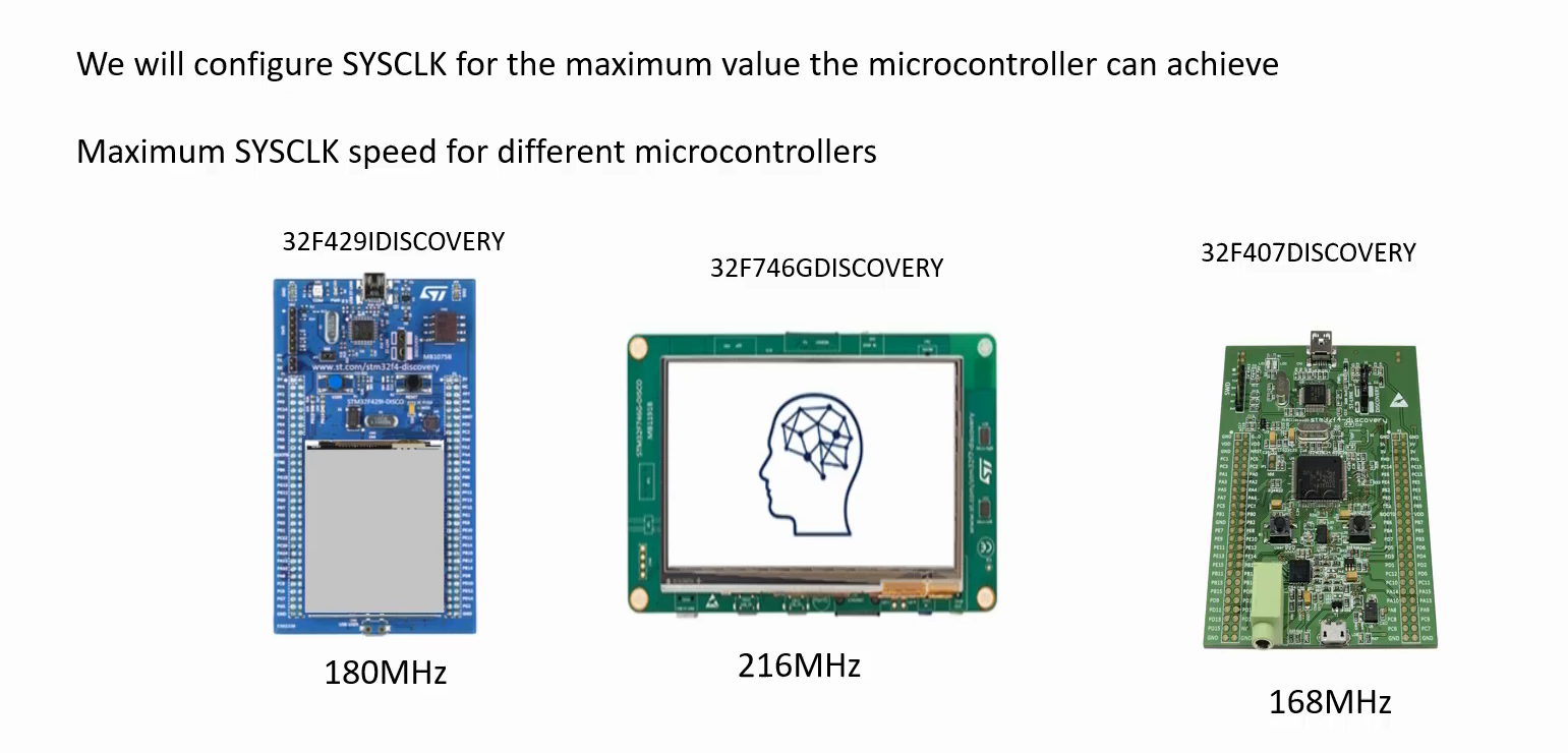
We will configure SYSCLK for the maximum value the microcontroller can achieve for the display VIBGYOR bars exercise.
In the microcontroller STM32F429IDISCOVERY board, the maximum value for the SYSCLK could be 180MHz. That is the maximum speed of the SYSCLK. And for this STM32F746GDISCOVERY microcontroller, it could be 216MHz, and for the STM32F407DISCOVERY board, it could be 168MHz.
For that, you have to use the PLL engine of the microcontroller.
Let’s explore the PLL engine and how to configure the system clock using the PLL engine of the microcontroller.
Main PLL configuration
- PLL_M(Controls input to the PLL VCO and PLLSAI VCO)
- PLL_N(Multiplier)
- PLL_P(Divider)
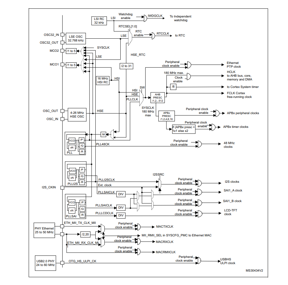
The Clock tree diagram is shown in Figure 2.
This Clock tree diagram explains the whole clocking engine of this microcontroller. And this clocking engine is almost the same in other microcontrollers of SD as well.
You should see a similar diagram, and if you just understand this, you can easily apply these points to any microcontroller of SD.
There could be some minor differences. Because, this clock tree looks complicated, but it is very simple because we should pay attention to only those points in which we are interested.
HSI, HSE, and PLLCLK is the main part of the clock tree.
Look at Figure 2, the main part of the clock tree is shown. So, where using the SW bit, we can select the SYSCLK out of these three options. HSI, HSE, and PLLCLK. And in this microcontroller, the maximum value of the SYSCLK could be 180 megahertz.
There are 3 options to select as SYSCLK.
HSI
One is HSI, which comes from the internal RC oscillator(HSI RC), which is 16MHz. By default, HSI is used as the main system clock. That means the SW bit by default selects HSI as the main system clock.
That’s why, on the STM32 microcontroller you need not to set up any clock, even the external clock oscillators nothing is required. Because the internal RC oscillator is always active. That’s why, you can always start working with your microcontroller without worrying about setting up the main system clock.
But for some exercises, this internal 16MHz of the clock may not be sufficient, like graphics applications where you need to update the frame buffer very quickly and you have to transfer buffers from one memory location to another memory location or to do some number crunching algorithms, etc. For those cases, you may need higher clock frequencies. That’s why we will boost this system clock to 180MHz in this application.
HSE
The second option is HSE. HSE comes from here (HSE OSC). This is a place where you connect the external clock oscillator. So, there is already an external clock present on your board that supplies 8MHz of a clock, that is the HSE.
PLLCLK
You can also see that the third option here is the PLLCLK. And this PLLCLK comes from the PLL engine.
PLL stands for Phased Locked Loop(PLL). And this contains a block called VCO(Voltage Controlled Oscillator), which produces high-speed clocks.
And for this block, you need to give the input. You can either give HSI as input or you can give HSE as input to the PLL. And that input directly goes to the VCO and VCO produces the output here. It multiplies the clock. I mean, it multiplies the input clock by using the multiplier option(xN). So, you have to configure the value of N.
This is where you get the output of the VCO, and the output of the VCO is divided by this factor /P, and this is the output clock of the PLL and then which is fed to the PLLCLK block, and then you can select it as the main system clock.
Now our job is to configure these parameters M, P, and N. We have to choose appropriate values for these parameters, then we can produce the appropriate clock which can be selected as the system clock.
- In this exercise, we are not using HSE, we are not using HSI, but we would like to have the PLL clock as SYSCLK.
And you can also see one more interesting thing here, the DOTCLK is produced from here in an LCD-TFT clock. That is our pixel clock or DOTCLK. And this is produced by the PLL SAI engine.
The PLL SAI engine is independent of the PLL engine.
Here you can see that, to control the LCD-TFT clock, you need to configure these parameters. DIV, xN, and R. And it also has got its own VCO, and the input of the VCO comes from here. That means input to this block is controlled by /M.
Now, we understood what is our next task, that is, we have to do the main PLL configuration. For that, we have to configure PLL_M, PLL_N, and PLL_P.
Where can we configure these values?
For that, there is one register. That is the RCC PLL configuration register (RCC_PLLCFGR).
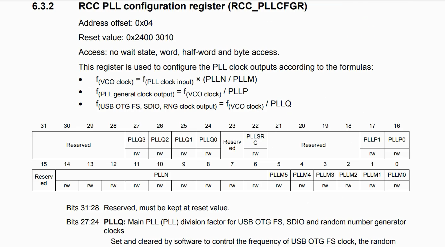
Here you can configure PLLP, PLLN, and PLLM(Figure 4). So, while configuring please read the caution section, because that is very important.
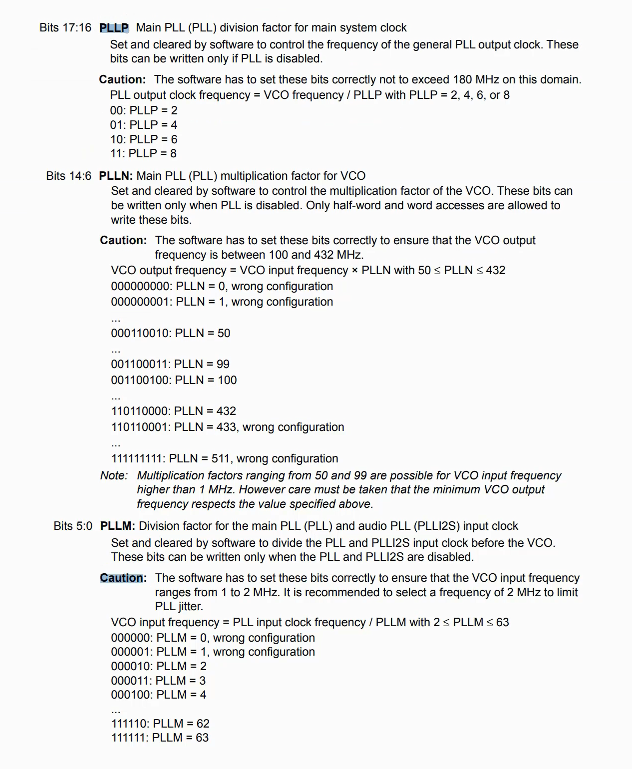
In the following article, we will code this into the RCC PLL configuration register. To program the registers we need to know the addresses of those registers in the memory map of the microcontroller. For that reason, we will use the microcontroller device header file.
The microcontroller’s device header file will contain all the base addresses of various bus interfaces and peripheral registers, and it also contains register details of various peripherals of the microcontroller.
Get the Full Course on STM32-LTDC, LCD-TFT, LVGL (MCU3) Here.
FastBit Embedded Brain Academy Courses
Click here: https://fastbitlab.com/course1

