Setting up main system clock code implementation part-1
In this article, we will begin creating the main clock code for our application. Having an accurate clock is essential for many applications and devices, and it’s no different in our case. The timekeeping module of our application is the backbone of the system, and we need to make sure that it is reliable and accurate.
The project has two header files: reg_util.h and stm32f429xx.h. These files contain essential information that we need to access the microcontroller’s registers and set up the clock.
The reg_util.h file contains some macros that we can use to configure the microcontroller’s registers. These macros are displayed in below. They make our code more readable and understandable by providing us with a shorthand notation for accessing the registers.
#ifndef REG_UTIL_H_
#define REG_UTIL_H_

/* Register bit manipulation macros */

#define REG_WRITE(reg, val) ((reg) = (val))
#define REG_READ(reg) ((reg))
#define REG_SET_BIT(reg,pos) ((reg) |= (1U << (pos)))
#define REG_CLR_BIT(reg,pos) ((reg) &= ~(1U << (pos)))
#define REG_READ_BIT(reg,pos) ((reg) & (1U << (pos)))
#define REG_CLR_VAL(reg,clrmask,pos) ((reg) &= ~((clrmask) << (pos)))
#define REG_SET_VAL(reg,val,setmask,pos) do {\
REG_CLR_VAL(reg,setmask,pos);\
((reg) |= ((val) << (pos))); \
}while(0)

#define REG_READ_VAL(reg,rdmask,pos) ((REG_READ(reg) >> (pos)) & (rdmask))


#endif /* REG_UTIL_H_ */
On the other hand, stm32f429xx.h is the device header file. As shown in below code, this header file contains various peripheral register structures. For instance, the peripheral register structure explains various registers of the ADC peripheral. Understanding these structures is important to configure the microcontroller’s registers accurately and efficiently.
#include <stdint.h>

/** @addtogroup Peripheral_registers_structures
  * @{
  */

/**
  * @brief Analog to Digital Converter
  */

typedef struct
{
  __IO uint32_t SR;     /*!< ADC status register,                         Address offset: 0x00 */
  __IO uint32_t CR1;    /*!< ADC control register 1,                      Address offset: 0x04 */
  __IO uint32_t CR2;    /*!< ADC control register 2,                      Address offset: 0x08 */
  __IO uint32_t SMPR1;  /*!< ADC sample time register 1,                  Address offset: 0x0C */
  __IO uint32_t SMPR2;  /*!< ADC sample time register 2,                  Address offset: 0x10 */
  __IO uint32_t JOFR1;  /*!< ADC injected channel data offset register 1, Address offset: 0x14 */
  __IO uint32_t JOFR2;  /*!< ADC injected channel data offset register 2, Address offset: 0x18 */
  __IO uint32_t JOFR3;  /*!< ADC injected channel data offset register 3, Address offset: 0x1C */
  __IO uint32_t JOFR4;  /*!< ADC injected channel data offset register 4, Address offset: 0x20 */
  __IO uint32_t HTR;    /*!< ADC watchdog higher threshold register,      Address offset: 0x24 */
  __IO uint32_t LTR;    /*!< ADC watchdog lower threshold register,       Address offset: 0x28 */
  __IO uint32_t SQR1;   /*!< ADC regular sequence register 1,             Address offset: 0x2C */
  __IO uint32_t SQR2;   /*!< ADC regular sequence register 2,             Address offset: 0x30 */
  __IO uint32_t SQR3;   /*!< ADC regular sequence register 3,             Address offset: 0x34 */
  __IO uint32_t JSQR;   /*!< ADC injected sequence register,              Address offset: 0x38*/
  __IO uint32_t JDR1;   /*!< ADC injected data register 1,                Address offset: 0x3C */
  __IO uint32_t JDR2;   /*!< ADC injected data register 2,                Address offset: 0x40 */
  __IO uint32_t JDR3;   /*!< ADC injected data register 3,                Address offset: 0x44 */
  __IO uint32_t JDR4;   /*!< ADC injected data register 4,                Address offset: 0x48 */
  __IO uint32_t DR;     /*!< ADC regular data register,                   Address offset: 0x4C */
} ADC_TypeDef;

typedef struct
{
  __IO uint32_t CSR;    /*!< ADC Common status register,                  Address offset: ADC1 base address + 0x300 */
  __IO uint32_t CCR;    /*!< ADC common control register,                 Address offset: ADC1 base address + 0x304 */
  __IO uint32_t CDR;    /*!< ADC common regular data register for dual
                             AND triple modes,                            Address offset: ADC1 base address + 0x308 */
} ADC_Common_TypeDef;
Moreover, stm32f429xx.h contains various base addresses of various blocks of the microcontroller. These addresses are crucial in configuring the microcontroller’s registers. Below code snippets show the base addresses for various blocks of the microcontroller.
For instance, if we want to configure the Timer2 peripheral, its registers start from APB1PERIPH_BASE + 0x0000UL base. This is the base address of the registers of the Timer2 peripheral. Understanding these base addresses is essential in configuring the microcontroller’s registers accurately.
/** @addtogroup Peripheral_memory_map
  * @{
  */
#define FLASH_BASE            0x08000000UL /*!< FLASH(up to 2 MB) base address in the alias region                         */
#define CCMDATARAM_BASE       0x10000000UL /*!< CCM(core coupled memory) data RAM(64 KB) base address in the alias region  */
#define SRAM1_BASE            0x20000000UL /*!< SRAM1(112 KB) base address in the alias region                              */
#define SRAM2_BASE            0x2001C000UL /*!< SRAM2(16 KB) base address in the alias region                              */
#define SRAM3_BASE            0x20020000UL /*!< SRAM3(64 KB) base address in the alias region                              */
#define PERIPH_BASE           0x40000000UL /*!< Peripheral base address in the alias region                                */
#define BKPSRAM_BASE          0x40024000UL /*!< Backup SRAM(4 KB) base address in the alias region                         */
#define FMC_R_BASE            0xA0000000UL /*!< FMC registers base address                                                 */
#define SRAM1_BB_BASE         0x22000000UL /*!< SRAM1(112 KB) base address in the bit-band region                          */
#define SRAM2_BB_BASE         0x22380000UL /*!< SRAM2(16 KB) base address in the bit-band region                           */
#define SRAM3_BB_BASE         0x22400000UL /*!< SRAM3(64 KB) base address in the bit-band region                           */
#define PERIPH_BB_BASE        0x42000000UL /*!< Peripheral base address in the bit-band region                             */
#define BKPSRAM_BB_BASE       0x42480000UL /*!< Backup SRAM(4 KB) base address in the bit-band region                      */
#define FLASH_END             0x081FFFFFUL /*!< FLASH end address                                                          */
#define FLASH_OTP_BASE        0x1FFF7800UL /*!< Base address of : (up to 528 Bytes) embedded FLASH OTP Area                */
#define FLASH_OTP_END         0x1FFF7A0FUL /*!< End address of : (up to 528 Bytes) embedded FLASH OTP Area                 */
#define CCMDATARAM_END        0x1000FFFFUL /*!< CCM data RAM end address                                                   */

/* Legacy defines */
#define SRAM_BASE             SRAM1_BASE
#define SRAM_BB_BASE          SRAM1_BB_BASE

/*!< Peripheral memory map */
#define APB1PERIPH_BASE       PERIPH_BASE
#define APB2PERIPH_BASE       (PERIPH_BASE + 0x00010000UL)
#define AHB1PERIPH_BASE       (PERIPH_BASE + 0x00020000UL)
#define AHB2PERIPH_BASE       (PERIPH_BASE + 0x10000000UL)

/*!< APB1 peripherals */
#define TIM2_BASE             (APB1PERIPH_BASE + 0x0000UL)
#define TIM3_BASE             (APB1PERIPH_BASE + 0x0400UL)
#define TIM4_BASE             (APB1PERIPH_BASE + 0x0800UL)
#define TIM5_BASE             (APB1PERIPH_BASE + 0x0C00UL)
#define TIM6_BASE             (APB1PERIPH_BASE + 0x1000UL)
#define TIM7_BASE             (APB1PERIPH_BASE + 0x1400UL)
#define TIM12_BASE            (APB1PERIPH_BASE + 0x1800UL)
#define TIM13_BASE            (APB1PERIPH_BASE + 0x1C00UL)
#define TIM14_BASE            (APB1PERIPH_BASE + 0x2000UL)
#define RTC_BASE              (APB1PERIPH_BASE + 0x2800UL)
#define WWDG_BASE             (APB1PERIPH_BASE + 0x2C00UL)
#define IWDG_BASE             (APB1PERIPH_BASE + 0x3000UL)
#define I2S2ext_BASE          (APB1PERIPH_BASE + 0x3400UL)
#define SPI2_BASE             (APB1PERIPH_BASE + 0x3800UL)
#define SPI3_BASE             (APB1PERIPH_BASE + 0x3C00UL)
#define I2S3ext_BASE          (APB1PERIPH_BASE + 0x4000UL)
#define USART2_BASE           (APB1PERIPH_BASE + 0x4400UL)
#define USART3_BASE           (APB1PERIPH_BASE + 0x4800UL)
#define UART4_BASE            (APB1PERIPH_BASE + 0x4C00UL)
#define UART5_BASE            (APB1PERIPH_BASE + 0x5000UL)
#define I2C1_BASE             (APB1PERIPH_BASE + 0x5400UL)
#define I2C2_BASE             (APB1PERIPH_BASE + 0x5800UL)
#define I2C3_BASE             (APB1PERIPH_BASE + 0x5C00UL)
#define CAN1_BASE             (APB1PERIPH_BASE + 0x6400UL)
#define CAN2_BASE             (APB1PERIPH_BASE + 0x6800UL)
#define PWR_BASE              (APB1PERIPH_BASE + 0x7000UL)
#define DAC_BASE              (APB1PERIPH_BASE + 0x7400UL)
#define UART7_BASE            (APB1PERIPH_BASE + 0x7800UL)
#define UART8_BASE            (APB1PERIPH_BASE + 0x7C00UL)
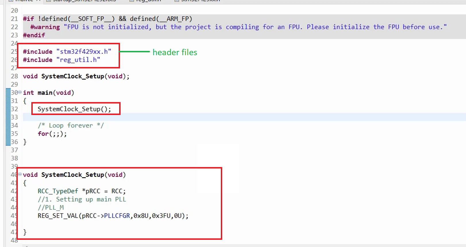
In the main program, we need to include these header files. We can use the following lines of code to include them:
#include “stm32f429xx.h”
#include “reg_util.h”
Then, we will write one function called SystemClock_Setup(). This function is responsible for setting up the main PLL.
To do that, we need to access the RCC peripheral of the microcontroller. We can create a variable to access the RCC peripheral of the microcontroller. So, we need to access the registers of the RCC block. The base address of the RCC registers is available in the device header file. We can create a variable of the RCC structure RCC_typedef, which we will call pRCC and this is equal to the RCC_BASE address. We can define it like this:
RCC_TypeDef *pRCC = RCC;
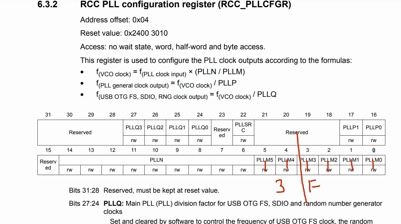
Once we have the pRCC pointer, we can set the value of PLLM. To do that, we have to access the RCC_PLLCFGR register, as shown in Figure 6. This is one of the registers of the RCC block. We have to configure the value of PLLM here by writing a new value to this register. Before doing that, we need to make sure that the PLLM bits are cleared first. This is important to avoid any unwanted values from previous configurations. To do that, we can use a macro called REG_SET_VAL, which takes the register value, a new value, a mask, and the position. The mask value is important as it helps clear the bits before setting a new value. The position value is the starting bit position of the value we want to set.
We can use the following line of code to set the value of PLLM with a value of 8:
REG_SET_VAL(pRCC->PLLCFGR, 0x8U, 0x3FU, 0U);

This line of code clears the register from the starting bit position using the mask value and sets the new value 0x8.

Like that, we can write the rest of the code for PLL_N and PLL_P configuration. Configuring the PLL is essential in setting up the main clock, and it is just one part of a much more comprehensive process.
Get the Full Course on STM32-LTDC, LCD-TFT, LVGL (MCU3) Here.
FastBit Embedded Brain Academy Courses
Click here: https://fastbitlab.com/course1


