ILI9341 LCD programming and data interface
The ILI9341 LCD driver chip is widely used for displaying graphical content in embedded systems. It is an affordable and easy-to-use display module that can be interfaced with various microcontrollers.
The ILI9341 is a popular LCD driver IC commonly used in small TFT LCD displays. It is capable of driving up to 320×240 resolution displays with 65K colors.
The next step is Configure the SPI peripheral.
Configuring SPI
- The SPI interface is used to send commands to the display module, which is based on the ILI9341 LCD driver Chip.
- For STM32F407x + external display setup, this interface is also used to transmit the RGB data.
In this blog post, we’ll discuss the programming and data interface of the ILI9341 LCD driver chip. We’ll start by discussing the basic interfacing of the chip with the STM32F429 Discovery board. Then we’ll move on to configuring the SPI peripheral for sending commands and data to the display module.
The STM32F429 Discovery board is a popular development board that can be used for interfacing with various peripherals, including the ILI9341 LCD driver chip.
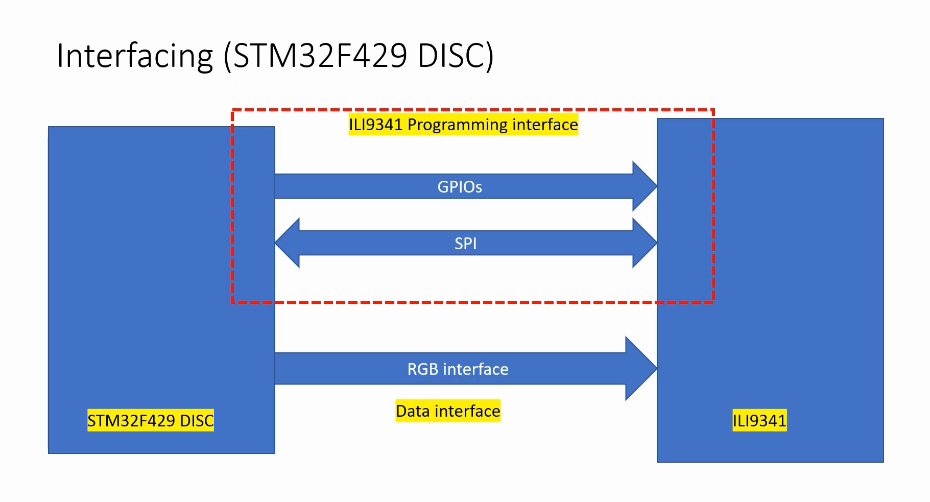
Here there are two interfaces.
- ILI9341 Programming interface
- Data interface
Data interface
A data interface is used to send RGB data.
ILI9341 Programming interface
This interface involves a couple of GPIOs and SPI communication.
Let’s see what the pins are involved in. To know more about the pins, you must visit and you must check the schematics. I’ll summarize here, as shown in Figure 2.
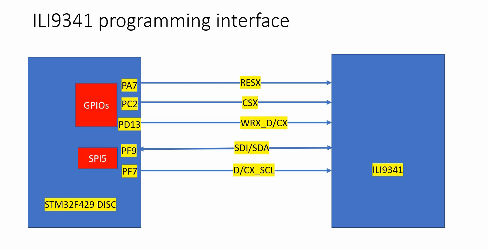
In the ILI9341 programming interface, 5 pins are used. 2 pins for SPI communication(SDI/SDA and D/CX_SCL) and 3 pins for GPIO communication(RESX, CSX, WRX_D/CX).
D/CX_SCL is an SPI clock. This is written like this, because I took this name from the schematic. Don’t get confused, it is just an SPI clock.
SDI/SDA is a bidirectional data line of the SPI. You can use this to write data and read data from the peripheral.
In STM32 microcontrollers, the SPI peripheral can be used in half-duplex mode. A single line can be used as a bidirectional data line. And on the STM32 microcontroller, a SPI5 peripheral has been used. So, you can’t change it. I mean, this is how the connection is on the board.
There are a couple of GPIOs being used for communication, as control signals. And let’s not worry about the purpose of these control signals. For that, we have to check the datasheet of ILI9341.
RESX, CSX, and WRX_D/CX are simple GPIOs. You must configure these GPIOs to output push-pull mode. Just configure them to output mode.
If you are using a STM32F407x+external LCD combination, there are a couple of GPIOs and SPI communication between these boards.
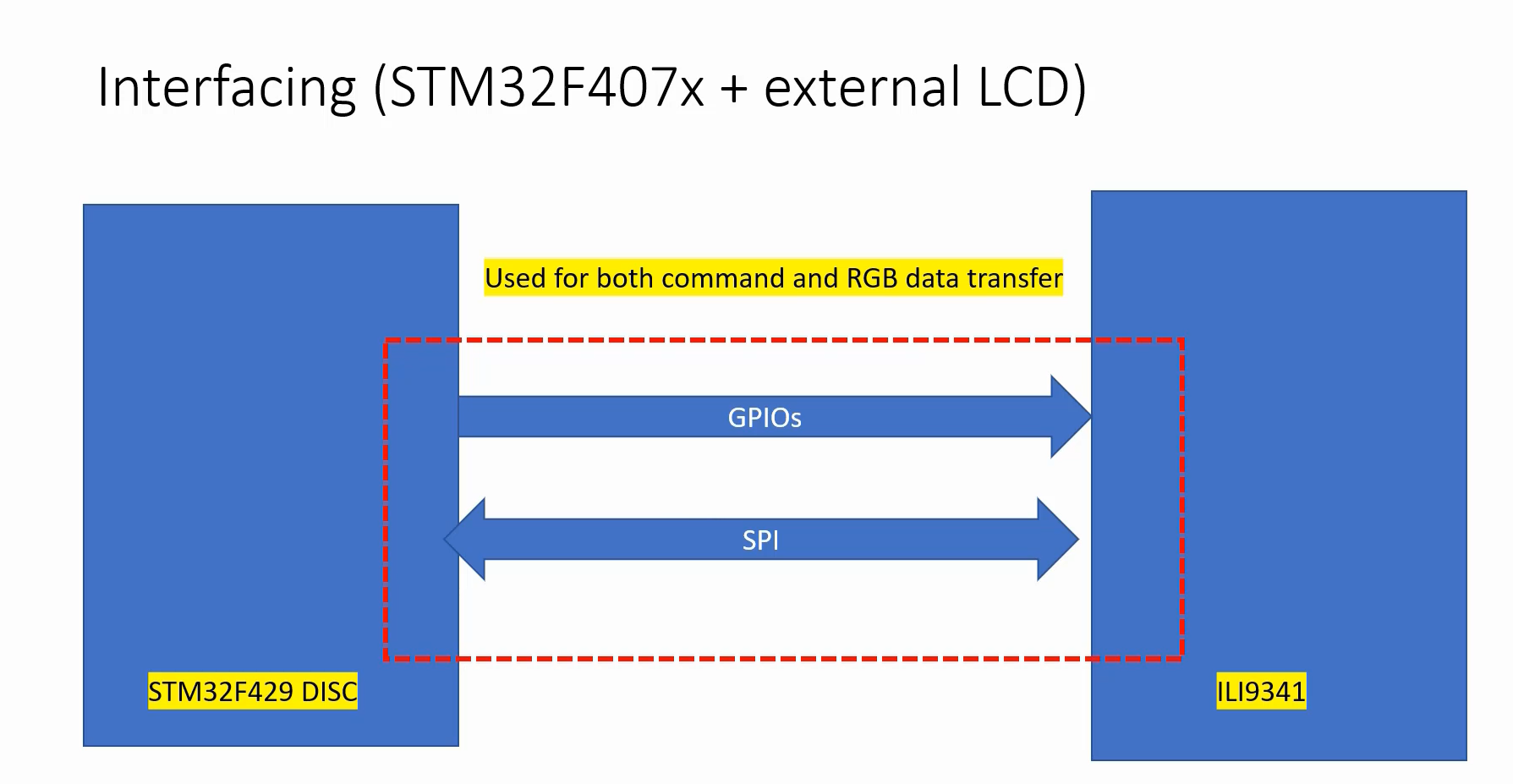
And you have to do the connections manually. SPI2 is used here, and 3 pins are used here(PB15, PC2, PB13) , a full-duplex communication. And the same three signals are also used in GPIOs.
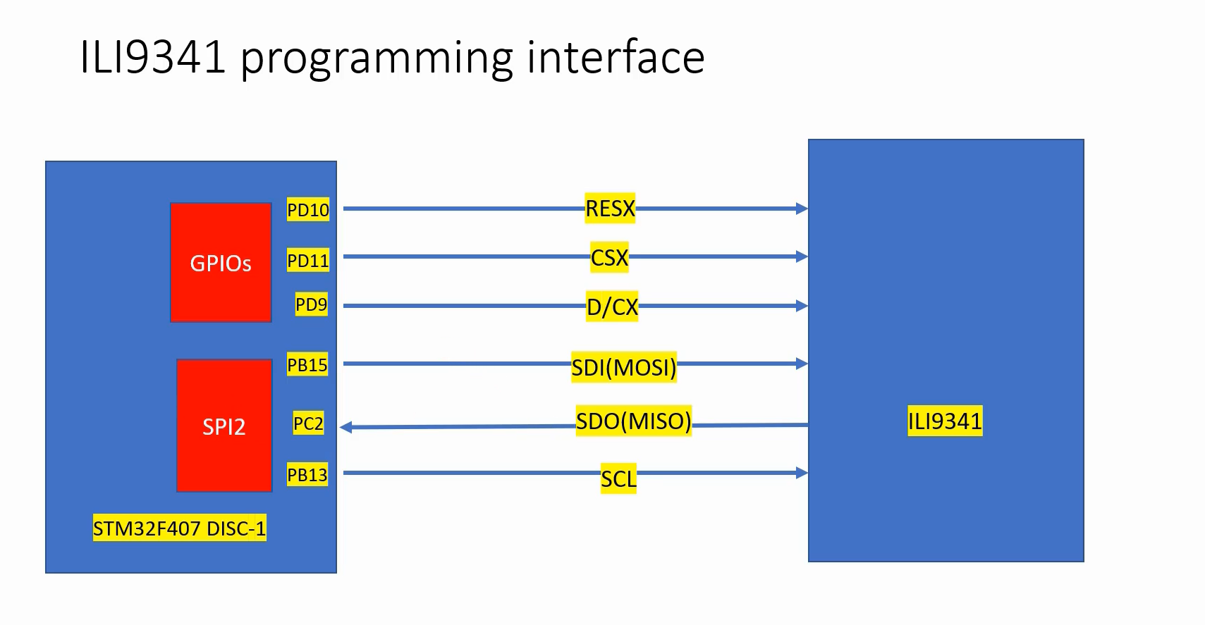
That’s about the connections.
FastBit Embedded Brain Academy Courses
Click here: https://fastbitlab.com/course1

