ILI9341 TFT-LCD Initialization commands
In this article, let’s understand the significance of the RESX, CSX, and DCX pins.
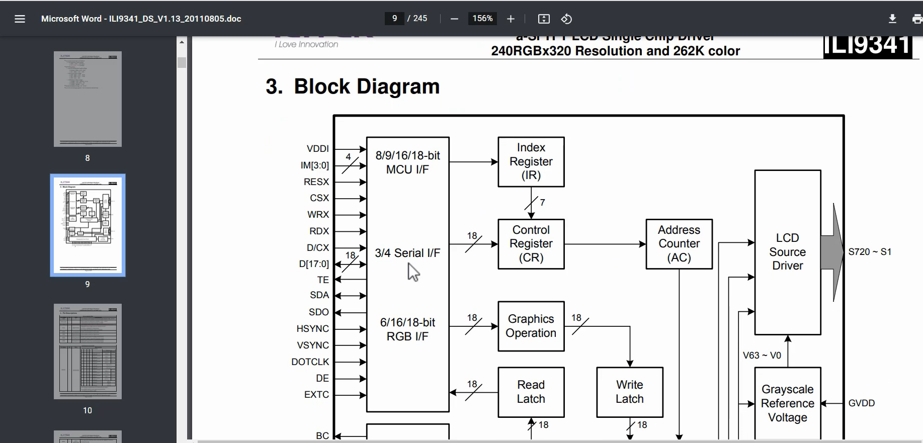
You can find RESX, CSX, D/CX signals in the datasheet of the ILI9341 chip. You can see Figure 1, these 3 signals are inputs to the chip.

All the pin descriptions you can see in the datasheet of the ILI9341 chip.

RESX
- This signal will reset the device and must be applied to properly initialize the chip.
- Signal is active low
CSX
- Chip select input pin “Low enable”.
- This pin can be permanently fixed “Low” in MPU interface mode only.
D/CX
- 8080 – I / 8080- II system(WRX): Serves as a write signal and writes data at the rising edge
- 4 line system (D/CX): Serves as command or parameter select.
In a 4-line system, specifically our SPI system, the D/CX pin functions as a command or parameter selector. When the D/CX pin is set to 0, any incoming data over the SDA line is treated as a command. On the other hand, if the D/CX pin is set to 1, the incoming data is treated as a parameter.
This is the fundamental purpose of these three pins.
Let’s set the initial state for the CSX, RESX, and D/CX signals. Keep the initial state of these three signals as high.
To do this, we can use the REG_SET_BIT function and select pGPIOC and the ODR register. The ODR register allows us to change the output status of a pin, setting it either high or low. If we set the pin state to high using the ODR register, the CSX signal will become high.
Similarly, we need to set the initial state for the RESX and D/CX signals as shown in Figure 3. To achieve this, we can follow the same procedure by using the REG_SET_BIT function to select the appropriate GPIO and ODR register.

If you want to explore the ODR register, you can navigate to the GPIO section, where you’ll find the registers and specifically the ODR (output data register).

You can see that it is not an atomic set or reset. For atomic bitset/reset, you can consult GPIOx_BSRR register.
We have made progress up to the point of configuring the SPI peripheral. Our next task is to set up the frame buffer for our application, but we will tackle that step later. For now, we need to focus on initializing the LCD module by sending LCD commands over SPI. This is necessary because the ILI9341 chip cannot be used without proper initialization. It is important to note that this step is not necessary for the STM32F746-DISC board.
To begin, we will explore the ILI9341 commands. We can refer to the datasheet for detailed information. The Command List section provides a list of different commands and command codes( Figure 5).

If you want to explore a specific command, a quick way to find it is by searching for its command code. For instance, if you’re looking for the command used to turn off the sleep mode of an LCD module, you can search for command code 11h, which corresponds to the Sleep Out command. This command is specifically designed to bring the module out of sleep mode and reactivate its display. By using command codes, you can easily locate the specific commands you need for your project without having to manually search through documentation or code.
Let’s see the LCD_config.
There are 2 commands here. And we have to implement this LCD_Write_Cmd.

LCD write command
The function LCD_Write_Cmd that takes an unsigned 8-bit integer (uint8_t) as an argument named cmd. The purpose of the function is to write a command to an LCD display using SPI (Serial Peripheral Interface) communication.
SPI_TypeDef *pSPI = SPI; – This line creates a pointer variable pSPI of type SPI_TypeDef and initializes it to the memory address of the SPI module (presumably defined elsewhere in the codebase).
LCD_CSX_LOW(); – This line appears to be calling a function to set the chip select (CSX) pin of the LCD display to a low logic level, indicating that the display is active.
LCD_DCX_LOW(); – This line also appears to be calling a function to set the data/command (DCX) pin of the LCD display to a low logic level, indicating that the subsequent data being sent over the SPI protocol will be a command (as opposed to data).
while(!REG_READ_BIT(pSPI->SR, SPI_SR_TXE_Pos)); – This line waits in a loop until the transmit buffer of the SPI module is empty (i.e., the TXE bit of the SPI status register is set to 1).
REG_WRITE(pSPI->DR, cmd); – This line writes the command value cmd to the SPI data register (DR) of the SPI module.
while(REG_READ_BIT(pSPI->SR, SPI_SR_BSY_Pos)); – This line waits in a loop until the SPI module is no longer busy (i.e., the BSY bit of the SPI status register is set to 0), indicating that the command has been successfully transmitted.
LCD_DCX_HIGH(); – This line sets the data/command (DCX) pin of the LCD display to a high logic level, indicating that subsequent data being sent over the SPI protocol will be actual display data (as opposed to a command).
LCD_CSX_HIGH(); – This line sets the chip select (CSX) pin of the LCD display to a high logic level, indicating that the display is no longer active.
In summary, this code defines a function for writing a command to an LCD display using SPI protocol, by setting up the SPI module, sending the command over SPI, and controlling the relevant pins of the LCD display.
LCD Write Data
The code you provided is a function called LCD_Write_Data() which writes data to an LCD display using SPI communication protocol. Here is a breakdown of what the code is doing:
- The function takes two arguments: a pointer to a buffer of data (uint8_t *buffer) and the length of the buffer (uint32_t len).
- It initializes a pointer to the SPI peripheral (SPI_TypeDef *pSPI = SPI;). This pointer is used to access the SPI control and data registers.
- The function enters a while loop that iterates len number of times, where len is the length of the buffer.
- Inside the while loop, the function sets the chip select (CS) line for the LCD to LOW (LCD_CSX_LOW()). This indicates to the LCD that data is about to be sent.
- The function then enters another while loop that waits for the Transmit Buffer Empty (TXE) flag in the SPI status register (SR) to be set (while(!REG_READ_BIT(pSPI->SR,SPI_SR_TXE_Pos))). This ensures that the SPI interface is ready to accept new data.
- The function writes the data from the buffer to the SPI data register (DR) using a register write function (REG_WRITE(pSPI->DR, buffer[i]);). This sends the data to the LCD.
- The function then enters another while loop that waits for the Busy (BSY) flag in the SPI status register (SR) to be cleared (while(REG_READ_BIT(pSPI->SR, SPI_SR_BSY_Pos))). This ensures that the SPI interface has finished sending the data.
- Finally, the function sets the CS line for the LCD to HIGH (LCD_CSX_HIGH()). This indicates to the LCD that the data transmission is complete.
In summary, the LCD_Write_Data() function sends a buffer of data to an LCD display over the SPI interface. It does so by setting the CS line low, waiting for the SPI interface to be ready, writing the data to the SPI data register, waiting for the SPI interface to finish sending the data, and setting the CS line high to indicate the end of the transmission.
And also define similar macros for RESX, CSX, and DCX, as shown in Figure 7.


A function LCD_Reset, which is used to reset an LCD display.
The function performs the following steps:
- Pulls the reset pin low
- Waits for 50ms (using a for loop)
- Pulls the reset pin high
- Waits for another 50ms (using a for loop)
To use the macros, you need to import the header file for lLI9341, which I have attached to the Inc folder. The file is called “ili9341_reg” and contains all the necessary command definitions.

You have to include that command here in bsp_lcd.c, as shown in Figure 10.

When you call the BSP_LCD_Init function from the main program, the Pin will be initialized, and the SPI peripheral will also be initialized. A Reset pulse will be sent to the display module, and LCD_config will send a few commands.

We will use the logic analyzer in the following article.
FastBit Embedded Brain Academy Courses
Click here: https://fastbitlab.com/course1


