LTDC pin initialization
LTDC stands for LCD TFT Display Controller, which is a peripheral in a microcontroller that can drive a TFT LCD display. The LTDC peripheral communicates with the display through multiple pins and ports, which need to be initialized properly to establish the communication.
To initialize the LTDC pins, first, you need to identify the pins involved in the RGB interface, control signals, and clock. Then, you need to configure these pins to the proper mode, which is the alternate function mode and set them to output push-pull mode.
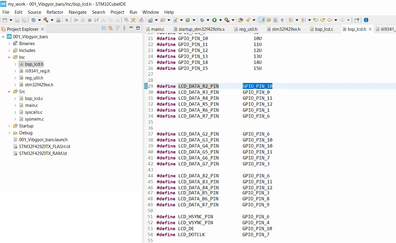
For example, the macro LCD_DATA_R2_PIN represents the pin number of the R2 data line in the LTDC RGB interface. Similarly, macros can be created for all the other RGB interface pins, control signals, and clock, shown in Figure 1.

For example, the macro LCD_DATA_R2_PORT represents the port of the R2 data line, which is GPIOC. You can get this information from the schematic of the microcontroller board or reference manual.
Once you have defined these macros, you can use them to initialize the LTDC pins by configuring them to the alternate function mode and setting them to output push-pull mode. This can be done using the GPIO initialization function provided by the microcontroller library.

To initialize the LTDC pins, you need to set them to output push-pull mode and set their alternate functionality to LTDC. To do this, you can use a loop that iterates over all the LTDC pins and initializes them one by one.
You have created an array called ltdc_io_ports[] that holds the addresses of each LTDC pin. This array is a pointer array, and each element is of type ltdc_pins[]. By indexing into this array, you can initialize each LTDC pin in a loop.

You need to implement these arrays in bsp_lcd.c, as shown in Figure 4. I have already populated the array *ltdc_io_ports with the addresses LCD_DATA_R2_PORT and LCD_DATA_R1_PORT, but you need to complete the rest of the array. This array holds all the pins, and the total number of pins will depend on how many entries you add to the array.

In main.c, we will create a function called LTDC_Pin_Init(). You can use a for loop to iterate through the ltdc_io_ports array. First, select the mode register and put it in alternate functionality mode. Then, do the same thing for output type selection, output speed selection, and programming the alternate function register.

Your task is to create macros for your board in bsp_lcd.h, and then complete the array and the LTDC_Pin_Init() function. Keep in mind that before you configure the GPIO pins, you must enable the clock for GPIO ports in the AHB1ENR.
FastBit Embedded Brain Academy Courses
Click here: https://fastbitlab.com/course1


