LTDC peripheral configuration part-2
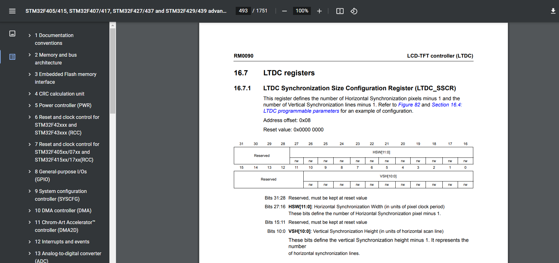
LTDC Synchronization Size Configuration Register:
The LTDC (LCD TFT Display Controller) Synchronization Size Configuration Register is a control register in the LTDC interface of microcontrollers that allows you to configure the synchronization signals for the display.
The synchronization signals are important for synchronizing the timing of the display data with the refresh rate of the display panel. The synchronization signals include horizontal and vertical sync signals, which are used to indicate the beginning of a new line and a new frame, respectively.
The LTDC Synchronization Size Configuration Register allows you to configure the number of pixels and lines for the horizontal and vertical synchronization signals. This information is used by the LTDC to generate the correct timing signals for the display.

In the datasheet you can see, HSW[11:0] Horizontal Synchronization Width(in units of pixel clock period). These bits define the number of Horizontal synchronization pixels minus 1. Suppose, if your LCD datasheet says, the HSW = 10, then you should store 9 here. So, 1 less.
The register typically contains fields for configuring the following parameters:
- Horizontal synchronization pulse width
- Horizontal back porch (the number of inactive pixels between the end of the active line and the beginning of the sync signal)
- Horizontal front porch (the number of inactive pixels between the end of the sync signal and the beginning of the active line)
- Vertical synchronization pulse width
- Vertical back porch (the number of inactive lines between the end of the active frame and the beginning of the sync signal)
- Vertical front porch (the number of inactive lines between the end of the sync signal and the beginning of the active frame)
In bsp_lcd.h, we define the HSW back porch, front porch, and horizontal and vertical synchronization timing numbers for our LCD modules, as shown in below code snippets.
Please note that the active width is 240 as per the datasheet. So, if you are using landscape mode, then you should swap the active height and active width values.
#ifndef BSP_LCD_H_
#define BSP_LCD_H_

#define BSP_LCD_HSW     10
#define BSP_LCD_HBP     20
#define BSP_LCD_HFP     10
#define BSP_LCD_VSW      2
#define BSP_LCD_VBP      2
#define BSP_LCD_VFP      4


#define BSP_LCD_WIDTH     240
#define BSP_LCD_HEIGHT    320
I just used a macro that starts from BSP_LCD_. So, to make it clear that these values are coming from the BSP files.
In the LTDC_Init function, first, we configure the horizontal synchronization timings.
For that, we should refer to LTDC Synchronization Size Configuration Register. Here we configure HSW and VSH(vertical synchronization height).
After that, go to LTDC Back Porch Configuration Register.

Here you should program the accumulated number of Horizontal Synchronization and back porch pixels minus 1.
You should add HSW and HBP values here, and 1 less.
For example, Look at above code snippet. Here HSW is 10 and HBP is 20, 10+ 20 = 30 and you should store 1 less, that is 29 here. And you do the same for verticals.
After that, go to LTDC Active Width Configuration Register.

Here accumulated active width, that is HSYNC width, that you know already HSW, HBP, Active Width.
After that, you have to configure the Total width.
Total width is HSYNC Width + HBP + Active Width + HFP – 1. You have to use this formula.

And then go to LTDC_GCR.

Here you can configure the polarities for various signals.
In our Program, polarity changing is not required, so we’ll use the default values.
In LTDC Background Color Configuration Register, you can configure the background color.
We want to use Red. Red means, blue is 0, green is 0, and makes all red bits high(1).

If you complete this much, and finally you enable the peripheral, you should start seeing the data on the display module.
Refer to the LCD-TFT Controller(LTDC) datasheet to get more information about LTDC registers.
FastBit Embedded Brain Academy Courses
Click here: https://fastbitlab.com/course1


