GPIO Programming Structure

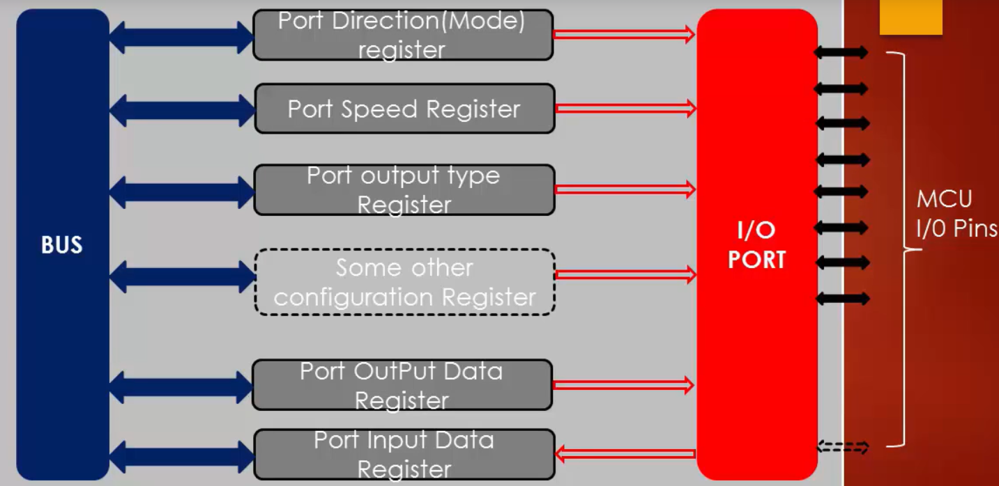
GPIO port is governed by many registers, as shown in Figure 1. These registers may vary depending on the vendors who design microcontroller.
The minimum set of registers that you find in any microcontroller is direction register, which is also called mode register. By using this register, you can set direction or mode as input, output, analog, etc..
Input data register which is used to read from a GPIO port and
Output data register which is used to write to a GPIO port.
In the STM32F4xx series of microcontrollers, each GPIO port governed by many configuration registers. They are:
- GPIO Port Mode register (GPIOx_MODER).
- GPIO Output Type register (GPIOx_OTYPER)
- GPIO Output Speed register (GPIOx_OSPEEDR)
- GPIO Pull Up /Pull Down register (GPIOx_PUPDR)
- GPIO Input Data register (GPIOx_IDR)
- GPIO Output Data register (GPIOx_ODR)
- GPIO Bit Set / Reset register (GPIOx_BSRR)
- GPIO Lock register (GPIOx_LCKR)
- GPIO Alternate Function register (GPIOx_AFRHand GPIOx_AFRL)
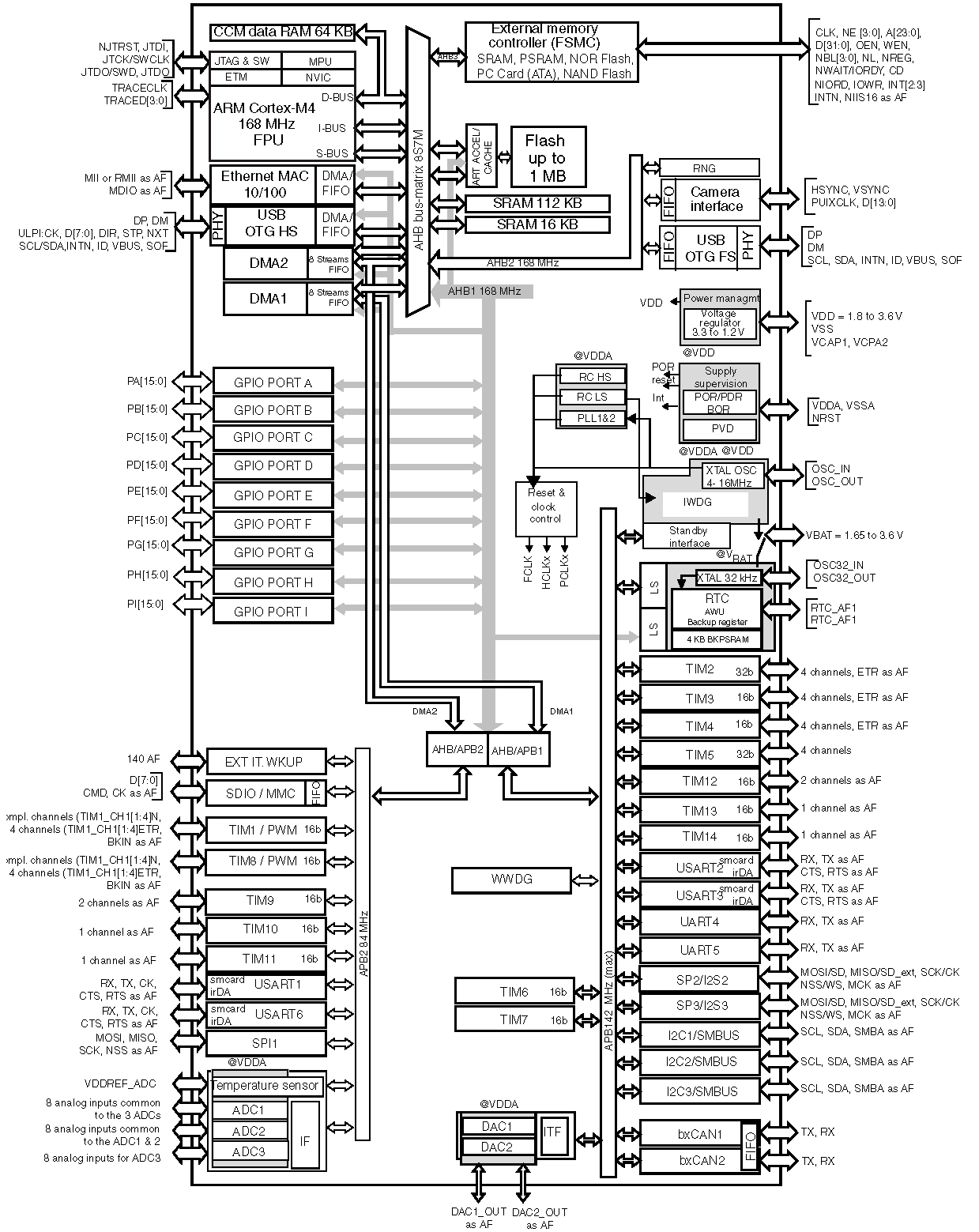
All these GPIO registers are connected over a system bus to the processor as shown in Figure 2.

In Figure 2. Shows that all GPIO ports connected to the processor over the AHB1 bus. AHB1 is a primary system bus that can operate at a maximum of 168 MHz clock speed.
In the following article, let’s explore GPIO PORT and PINs of STM32F4xx discovery board.
FastBit Embedded Brain Academy Courses,
Click here: https://fastbitlab.com/course1


