GPIO input mode with pull-up /pull-down state
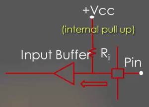
Let’s understand the GPIO pin in input mode with external or internal pull-up/pull-down resistor connected, as shown in Figure 1 and Figure 2.
It’s a simple circuit in which the floating state is avoided by introducing or activating internal pull-up /pull-down resistor.
In Figure 1 internal pull-up resistor is enabled, which drives pin to high voltage.
In Figure 2 internal pull-down resistor is activated, which drives pin to the ground.
- Pull-up Resistor: A pull-up resistor connects the GPIO pin to the supply voltage (Vcc or +5V) through a resistor. This ensures that when the external signal is disconnected or high impedance, the pin is pulled to a logic high state. When the external signal connects to ground, it can override the pull-up and pull the pin to a logic low state.
- Pull-down Resistor: Conversely, a pull-down resistor connects the GPIO pin to ground (GND) through a resistor. In this case, when the external signal is disconnected, the pin is pulled to a logic low state. When the external signal connects to the supply voltage, it can override the pull-down and pull the pin to a logic high state.
How to activate the internal pull-up/pull-down resistor?
There is configuration resistor for every GPIO port which enables us to handle internal pull-up /pull-down resistor. GPIO configuration resistors are GPIOx_MODER, GPIOx_OTYPER, GPIOx_OSPEEDR, and GPIOx_PUPDR.
Please note that it’s always safe to keep unused GPIO pins in one of the states. So, the remaining GPIO pins are reluctant to voltage fluctuations which may lead to the leakage of the current.
Many microcontrollers supply internal pull-up/pull-down configuration options. Sometimes, a specific pull-up/pull-down resistor value required which necessitates using an external pull-up/pull-down instead of a chip’s internal pull-up/pull-down.
FastBit Embedded Brain Academy Courses,
Click here: https://fastbitlab.com/course1


