GPIO output speed register and its applicability
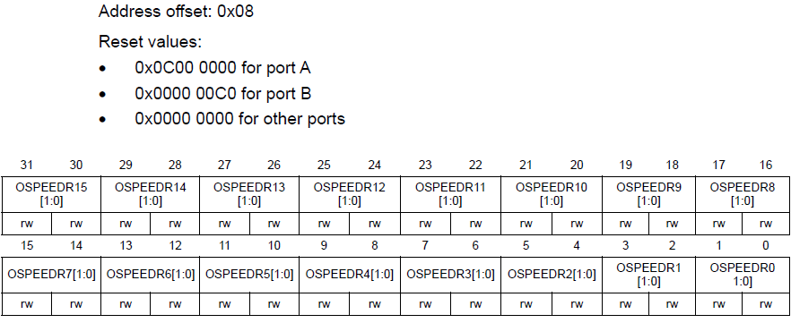
GPIO output speed register means, as the name indicates the configuring speed register and it is only applicable when the GPIO pin is in output mode. GPIO speed register controls the slew rate or the rate at which a signal can change between low/high values (the “rise time” and “fall time”).

The I/O speed can be configured as:
00: Low speed
01: Medium speed
10: High speed
11: Very high speed

By using the GPIO output speed register, one can configure the GPIO transitions from high to low and low to high, which means the slew rate of a pin can be controlled by GPIO output speed register.
So, the output speed register controls the slew rate of the GPIO switching.
From the Figure2 T rise is called as the amount of time GPIO takes from low to high and T fall is the amount of time taken from the GPIO pin to switch from high to low. If you want to control this T rise and T fall you have to use GPIO output speed register.
If you select GPIO pin as low speed, that is if the speed register is 00, then the maximum achievable switching frequency of that GPIO pin will be 8MHz. For medium speed, then the maximum frequency is up to 50MHz. For maximum high-speed frequency up to 100MHz. For very high-speed maximum switching frequency up to 180Mhz.
By increasing the GPIO speed, you increase the rate of change of the output voltage (reducing rise time). However, power consumption and noise radiated by the circuit increases along with the GPIO speed.
By default, you should keep GPIO speed low unless there is a specific reason for increasing it.
In the following article, let’s see GPIO Pull-up and Pull-down registers.
FastBit Embedded Brain Academy Courses
Click here: https://fastbitlab.com/course1


