I2C IRQ handler implementation Part 5
In this article, let’s discuss the creation of the handle for the interrupt generated by the setting of the TXE flag.
When the TXE flag is set, that indicates that the data register is empty, and the software has to put a data byte into the data register to send that data byte to the external world.
Steps to be followed when the TXE flag is set:
- When a TXE flag is set, you have to do the data transmission.
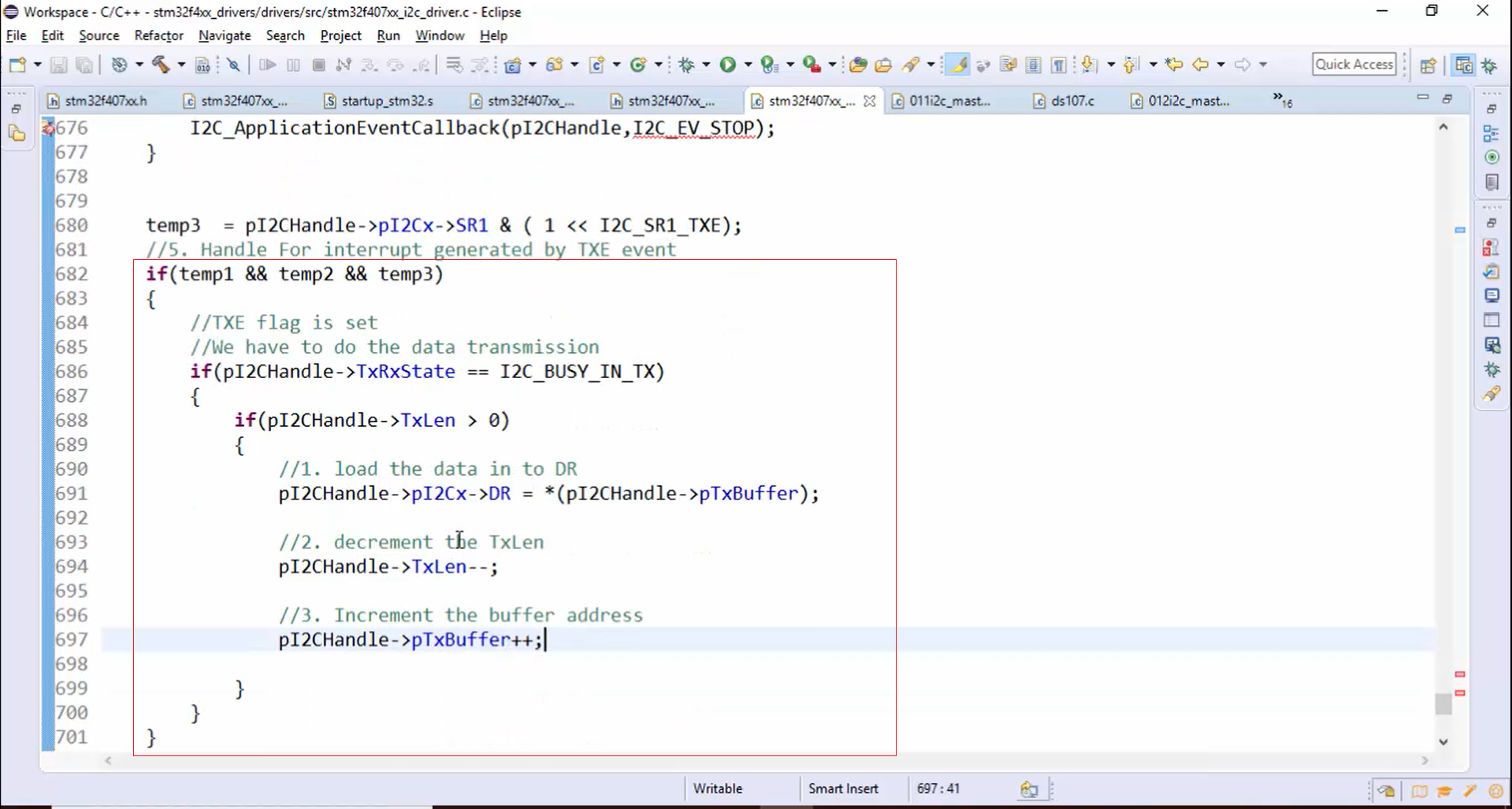
- Before starting the data transmission, first, confirm the application’s state. The data transmission must begin only if the application state is busy in TX. Let’s check the application’s state by using the if statement, as shown in Figure 1.
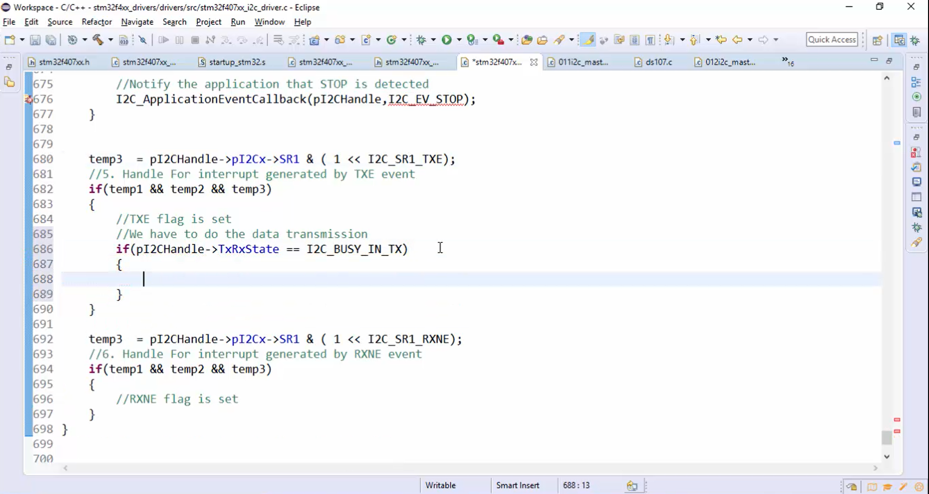
- If the application’s state is busy in TX, then start the data transmission as follows:
- First, check whether the length value stored in the TxLen variable is greater than 0 or not (Figure 2).

- If the length is greater than zero, then load the data into DR (Figure 3).

- Decrement the TxLen variable (Figure 4).
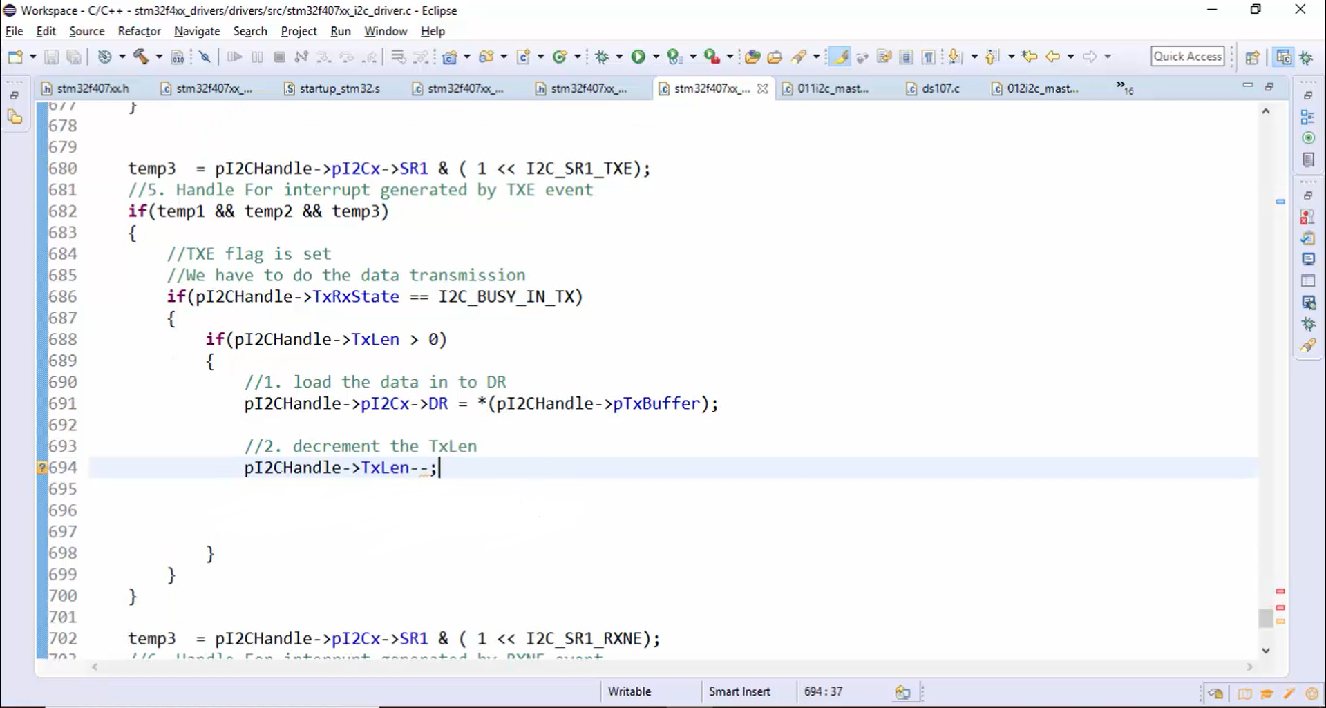
- Increment the buffer address (Figure 5).

Whenever the TXE is set, the control will enter into the if statement, shown in Figure 6. If the application’s state is busy in TX and the length is greater than 0, then 1 byte will be transferred to the DR.
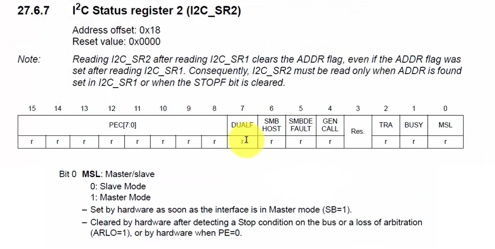
All the tasks in Figure 6 must be performed only when the device is master. Therefore, before performing these tasks, you should confirm whether the device is master or not. At any point in time, you can ensure the device mode by checking the MSL bit of the status register (Figure 7). If the MSL bit is set, then you can say that the device is behaving as master. Otherwise, the device will be in slave mode. This bit is set by the hardware as soon as the interface is in Master mode (SB=1) and cleared by the hardware after detecting the stop condition on the bus or loss of arbitration or when PE=0.
Now let’s check the device mode, as shown in Figure 8.


