Target preparation : Serial debug setup
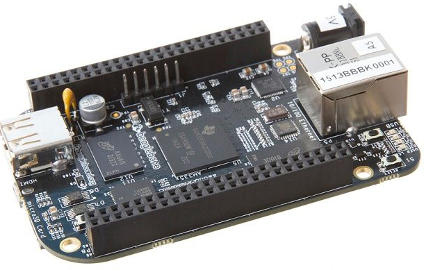
In this article, we will focus on the essential target preparation steps for your BeagleBone Black (BBB) device, as depicted in Figure 1.
Board Components
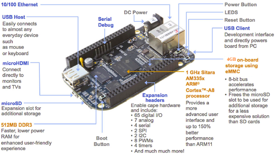
Before diving into setup details, let’s take a moment to familiarize ourselves with the various components of the BBB, as illustrated in Figure 2.
About the board Beaglebone black Board(BBB)
The board is a Beaglebone black board(BBB), and the heart of this board is a SOC from Texas Instruments.
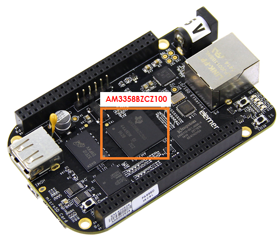
This SOC is from the Sitara family and produced by Texas Instruments.
The exact part number is AM3358BZCZ100 (Figure 3). And this SOC is based on the ARM Cortex A8 processor, which is of ARMv7 architecture of ARM.
Embedded MMC (eMMC)
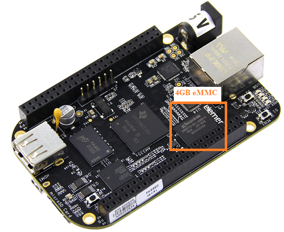
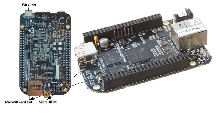
And apart from this SOC, this has onboard eMMC(Figure 4), and it has got a microSD card slot, where you can connect the microSD card, it has a USB host, HDMI interface as in (Figure 5), it has Ethernet and so many other things.
Boot Options
You can boot this board through various interfaces; you can boot the Linux kernel through eMMC or SD card, USB, Ethernet, SPI. There are multiple options available. This board comes with a free installed OS, the Debian OS on eMMC, and by default, this board boots via eMMC that is embedded MMC.
That’s why, when you give power to this board, the Debian OS, which is stored in the eMMC, runs.
In this, we will not be touching the eMMC memory of the board, Instead, we are going to install the Debian root file system and our boot images on the SD card, and we boot via the SD cards so that your eMMC files will not get affected.
Powering the BeagleBone Black
First, let’s learn how you can supply power to this board.
Powering the BBB is a straightforward process. You’ll need a mini USB cable, which typically comes with the board. So if it doesn’t come with the board, then you may have to buy one.
Connect one end of the cable to your PC and the other to the BBB’s mini USB port, located near the Ethernet slot, as demonstrated in Figure 6.
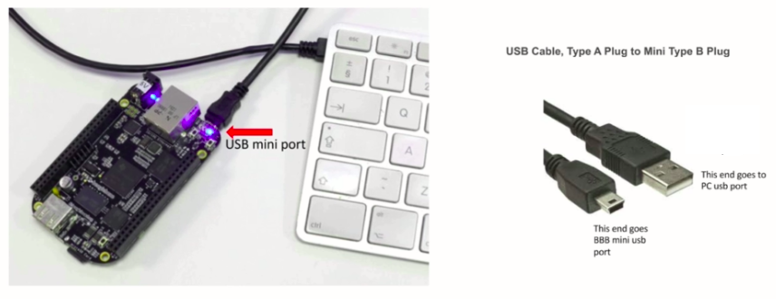
That’s how you power the board.
Serial Debug Port Connection
For effective debugging and early boot message capture, you’ll require a Serial debug cable.
Serial debug cable is a very useful cable. This cable helps you to establish the connection(as shown in Figure 7.) between the computer and the target, that is, the Beaglebone blackboard.
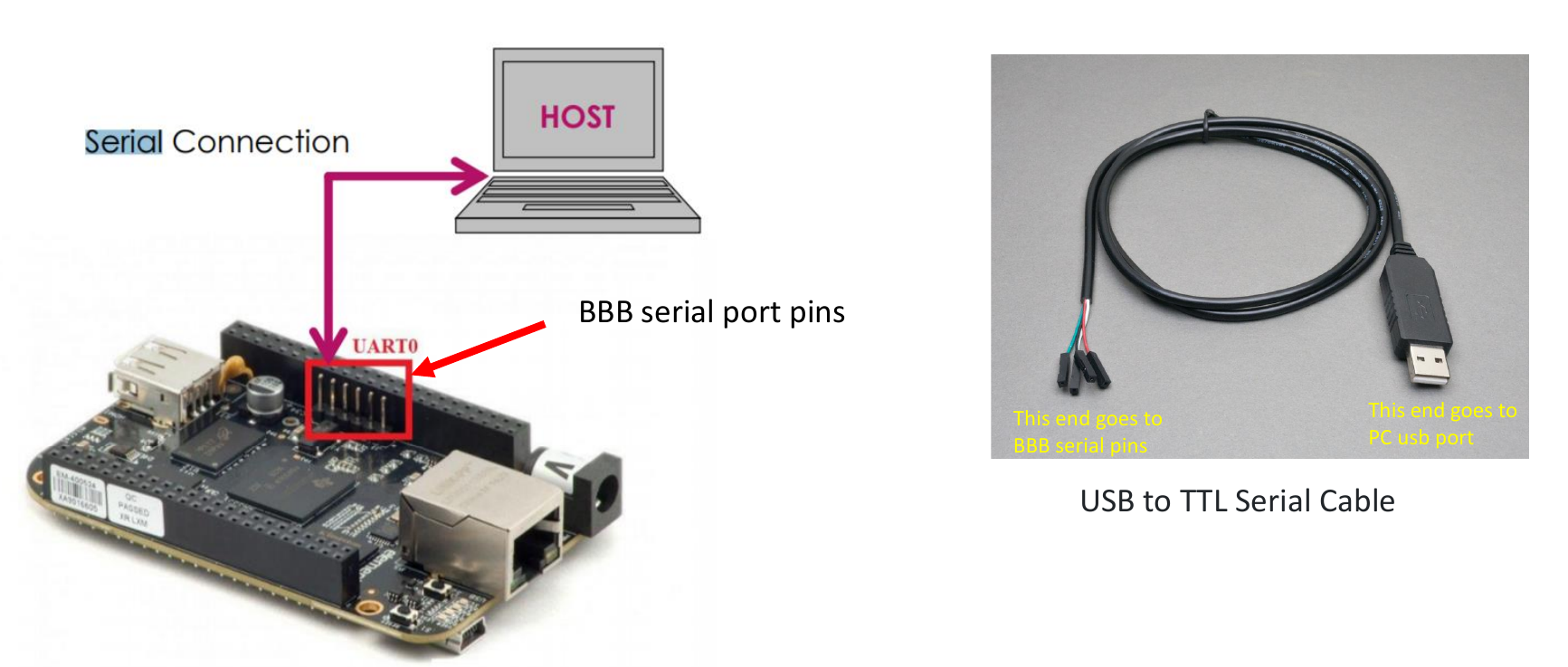
When Linux boots on the hardware, it actually emits the early boot messages on the serial pins.
So, the serial pins are exposed on the board; these are the beagle bones serial port pins. Using this cable, we can get those debug messages on our computer.
Instead of this cable, you can also go for dongles, USB to TTL serial converter dongles. I would not suggest buying these dongles because this would make your setup messier. Because it doesn’t come with a cable. You have to arrange for the cables like jumper wires and all. That’s why to go for USB to TTL serial converter cable instead. This is a very low-cost cable; you can get it for 3 to 4 dollars.
Making Connections
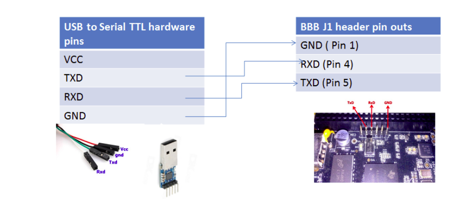
When connecting the USB to TTL serial converter cable to the BBB, we have to make a cross-connection. That means TX must go to the RX, and RX should go to the TX.(Figure 8)
Here, you take the ground pin of the cable; the ground pin is black in color.
The ground pin of the USB to serial cable must be connected to the ground pin of the beagle bones J1 header;That is Pin 1.
Specifically:
- Ground (USB to TTL) -> Pin 1 (BBB’s J1 header)
- TXD (USB to TTL) -> Pin 4 (BBB’s J1 header)
- RXD (USB to TTL) -> Pin 5 (BBB’s J1 header)
By following these steps, you’ll be well-prepared to commence your BeagleBone Black development journey with an efficient serial debug setup.
In an upcoming article, let me explain the boot sequence of the Beaglebone Black hardware.
FastBit Embedded Brain Academy Courses
click here: https://fastbitlab.com/course1

