Booting sequence of Beaglebone Black hardware
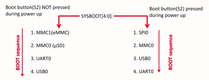
In this article, let’s explore the Boot sequence of BBB. There are different Boot sequences possible, as shown in Figure 1, and you can also alter the boot sequence.
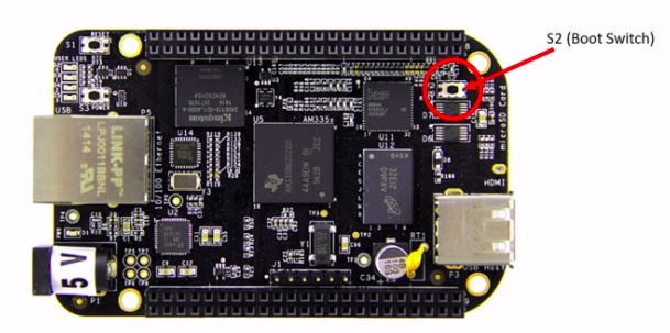
To alter the boot sequence, there is a boot button on the board, and the boot button is S2, as shown in Figure 2.
If you don’t press the boot button and if you give the power to the board, then this boot sequence will be followed, as shown in Figure 3.
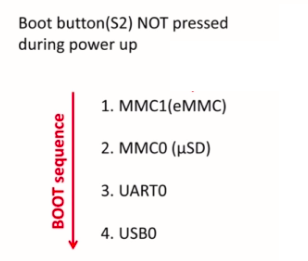
That means the hardware will first try to boot from the onboard eMMC, that is, embedded MMC.
If it doesn’t find any valid partition, then it would check the next boot source, that is, the SD card. If it doesn’t find any valid boot images over there, then it would go to UART0, and then it would try to boot from USB0.
That’s a default boot sequence if you don’t press the boot button. As I said already, the board already comes with a pre-installed Debian OS on the eMMC. That’s the reason whenever you give power to the board, the board boots from the eMMC. You need not press anything. Just give the power to the board it boots.
But, in our case, we don’t want to boot from the eMMC. Remember that. We want to boot from an SD card. That’s why we have to go above the boot sequence(Figure 3).
You have to press the boot button during power-up. Whenever you give power to the board, the boot button must be pressed. In that case, the first boot source becomes SPI, which would be invalid in our case that’s why the board tries to boot from MMC0, which is nothing but a MicroSD slot.
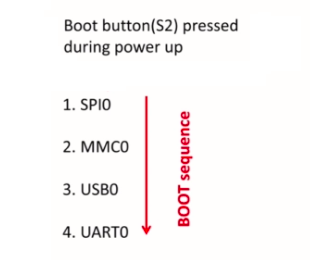
We have to keep valid partition and valid boot images on the SD card so that the board can boot from the micro SD card. In our case, this would be the boot sequence( refer to Figure 4).
But you need not to keep pressing the boot button S2 again and again during power-up; there is one hack, which I will cover in later articles. That we can make our board boots from the microSD card whenever we give power to the board, we will explore that later.
![Figure 5.SYSBOOT[4:0]](https://fastbitlab.com/wp-content/uploads/2022/01/Figure-5-5.png)
Actually, the boot button S2 affects a register called SYSBOOT(Figure 5).
SYSBOOT is a register, or it is a bit field of a control register of the SOC. A pressing or not pressing of the S2 button affects the contents of the SYSBOOT. That’s what makes the board to select between different boot sequences. Here is an S2 button(in Figure 6); this is a boot button.
Just check your board near the microSD card slot, you see one button, that is the boot button named as S2.
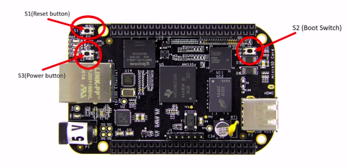
And you also see two more buttons. One is the power button, and another one is the reset button(Refer Figure 6.)
Let’s understand the use case of these power button, reset button, and boot button.
- Power button: By pressing and holding this button for 10 to 20 seconds, you can power down the board. Once you power down the board, gently pressing this button one time will again power up the board. Instead of connecting and disconnecting power sources to your board now and then, you can use this button to power down and power up.
- Reset button: Pressing this button resets the board. Note that the boot sequence is not affected by the reset action.
- Boot button: You can use this button to change the boot sequence during power up the board.
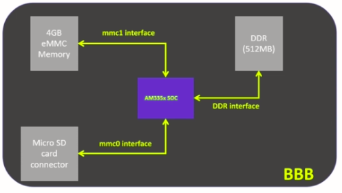
In summary, our board has got two important interfaces (Figure 7). The SOC can boot from the embedded MMC, which is of 4 gigabytes, or our SOC can boot from an external interface such as a MicroSD card connector.
The Micro SD card connector is called as MMC0 interface, and onboard eMMC is called as MMC1 Interface.
As I said before, we will not be booting from the MMC1 interface; we will be booting from the MMC0 Interface that is the Micro SD card. I will cover booting from the Micro SD card interface in the upcoming article.
Get the Full course on Linux Device Driver Here
FastBit Embedded Brain Academy Courses
Click here: https://fastbitlab.com/course1