Exercise-003 Data structure explanation
In the previous article, we set up the IDE, and in this article, let’s start implementing.
The first step is to create a few more header files and source files for our project.
We have got main.cpp. The extension is ‘CPP’ here, the C++ file, because the Arduino framework uses the C++ programming language. But we will code using the C programming language syntaxes.
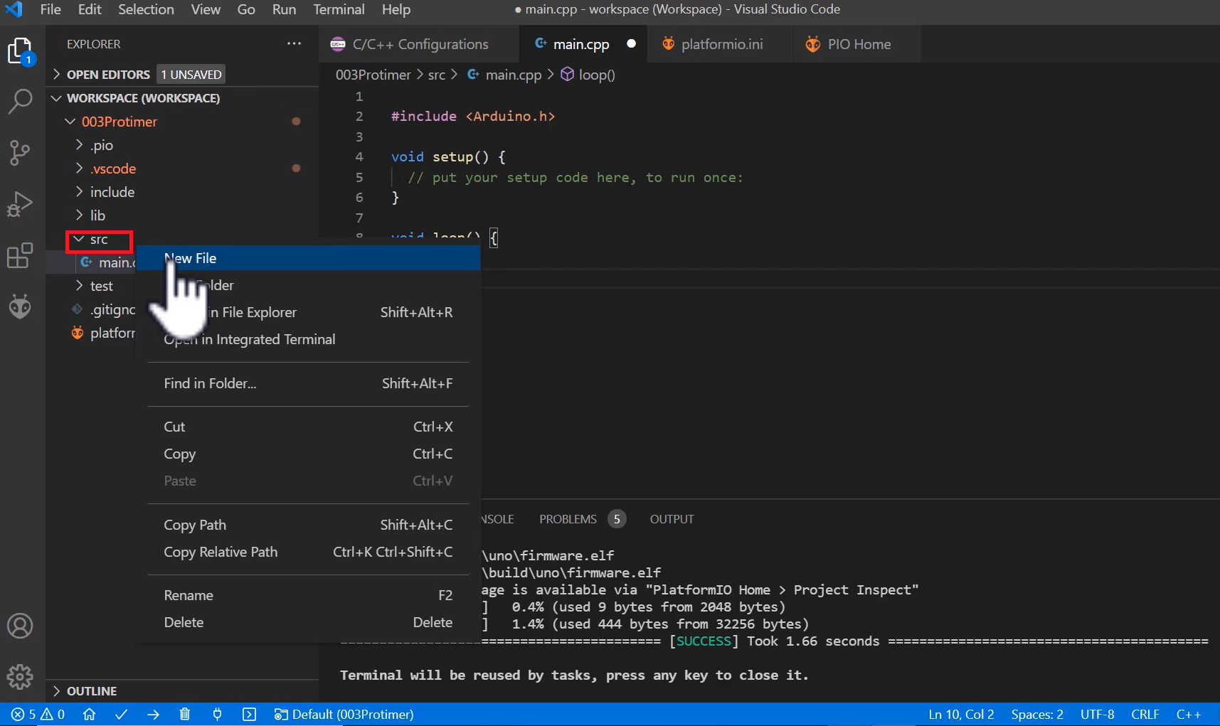
Let’s create a header file, as shown in Figure 1.
- Just select src, right-click, new file, and let me call it ‘main.h’, a header file.
- And also, we are using LCD in this project; create ‘lcd.cpp’, a source file to keep LCD-related code.
- And also one more file ‘lcd.h’.
- And also, let’s segregate the state machine implementation into a separate file. I will call it protimer_state_machine. This file is a .cpp file, where we will keep all state machine implementation. That is the state machine diagram implementation. Instead of putting all the code into main.cpp, I’m just segregating this.
In the main.cpp, #include “main.h” as shown in Figure 2.

The Arduino.h, you just keep in the main.h file, which is required if you are using the PlatformIO Extension (Figure 3).

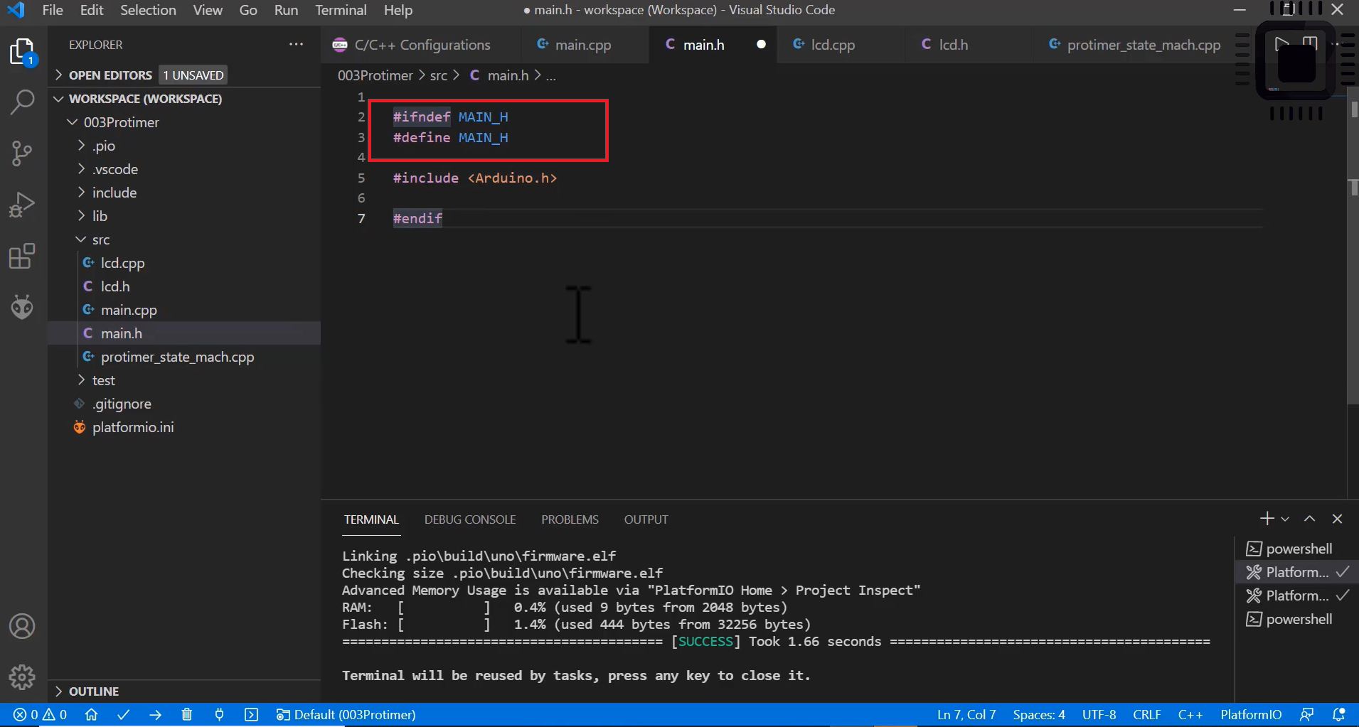
In the main.h, let’s give include guards. The red line shows the include guards in Figure 4 and ends that if statement using ‘endif.’ And in the lcd.h file, we also use include guards.
Data structures
- Define various signals of the application using enum
- Define various states of the application using enum
- Define the main application structure
- Define structures to represent events
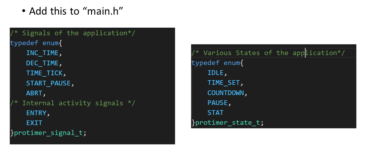
First, Signals and States. You just add all the definitions(Figure 5) to “main.h”. I have just used an ‘enum’ to represent various application signals. Also, I have included ENTRY and EXIT enumerators. They are 2 represent the internal activity signals.
And after that, create one enum definition for various states of the application, as shown in figure 5.
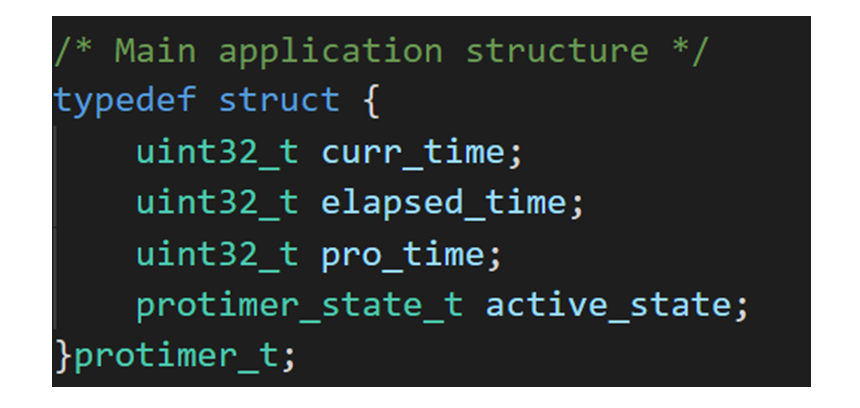
After that, the main application structure. You should also keep it in main.h, as shown in Figure 6. It shows the variables; you can also call them extended state variables.
Current time, elapsed time, and productive time are unsigned values. And also, there is one state variable, active_state, that holds the current active state of this main application object.
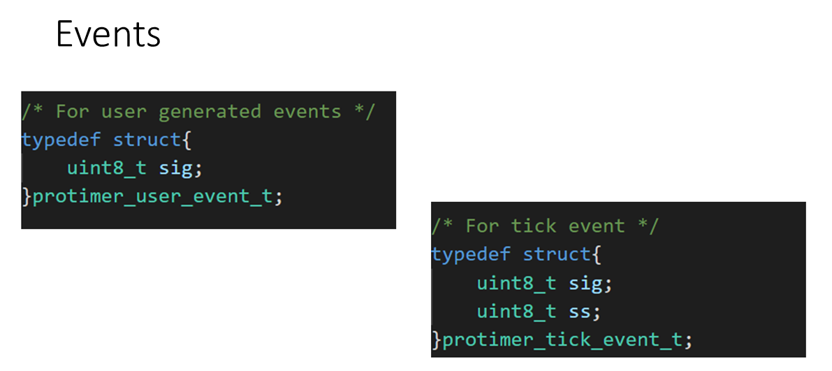
And after that, the Events, we have got two types of events in this application. User generated and system generated events.
The user-generated event has only the signal component and doesn’t have any associated parameters. Create one structure protimer_user_event_t, and just use one variable ‘signal’ as the member element to represent the signal. (Figure 7)
And after that, for tick events, this is system generated, or it’s a synchronous event. And it has two components, ‘Signal’ and the associated parameter ‘Sub-second.’
Instead of doing this, there is one disadvantage with this approach.
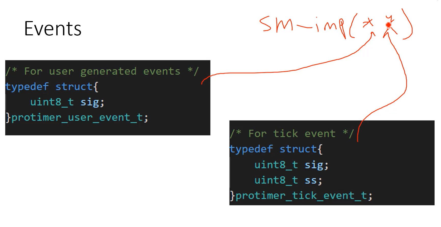
Let’s say you have a state machine function or state machine implementation. And for the state machine implementation, you have to pass the event.
Events are represented as structures. Sometimes you have to pass user-generated events, and sometimes you have to pass system generated events(shown in Figure 8). That means now there should be two receiving parameters. That doesn’t look good.
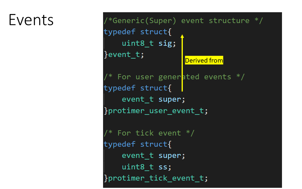
What you do is you create one super event structure or generic event structure, called event_t, and you include the signal value there(shown in Figure 9).
This method’s advantage is that you can just send a pointer to this member element. And then downcast to get the parent structure address.
FastBit Embedded Brain Academy Courses
click here:https://fastbitlab.com/course1

