Atmega328p Timer registers and setup code
Atmega328p Timer registers and setup code
In the main.cpp, I just added a function Timer1_setup; here, we will configure the Timer1 peripheral of the microcontroller to generate an interrupt for every 100 milliseconds.
static void Timer1_setup(void){
   TCCR1A = 0; //CTC mode
   TCCR1B = B00001100; //prescaler=256,CTC mode
   TIMSK1 |= B00000010; //Interrupt enable for OCR1A compare match
   OCR1A = 6250-1; //OC match value for 100ms time base generation
}
Timer1_setup function
As I explained in the previous article, I will be configuring the Timer1 peripheral in CTC mode. To configure the timer in CTC mode, you have to explore the register description. Let’s go to the register description.
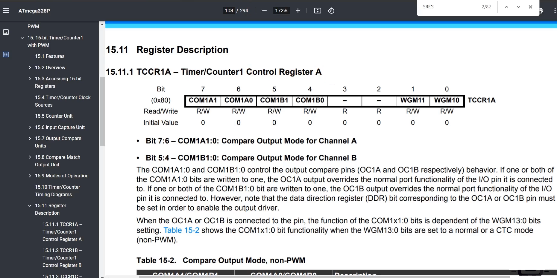
First, let’s start with the first register of the Timer1 peripheral. That is TCCR1A – Timer/Counter1 Control Register A.
Here, you see in Figure 2 that we need not use these bits. Because, for example, here, let’s start with the 0th field.

You can see that bit 0 and 1, which stands for Waveform Generation mode(WGM), can be used to choose the mode. I’m going to keep these bits to represent the CTC mode. For that, WGM11 and WGM10, 2 bits must be 0, WGM12 bit must be 1, and WGM13 must be 0.
Here you will get WGM10 and WGM11. WGM12 and WGM13 you get in the next register, so we’ll see that. As per that table, it is confirmed that we have to keep WGM10 and WGM11, these bit fields as 0.
Now, let’s see 4, 5, 6, 7, bit fields. You see Figure 2, Bit5:4 – Compare output mode for Channel B. These bits are not required because these are used to control the OC1A and OC1B pins. I want it to be disconnected; that’s why we will select 0 here. So, we’ll choose 0 for these four bit fields (4, 5, 6, 7, bit fields) because that is to do with the wave generation. That’s why it turns out to be 0.
So, that’s why I copy the register name TCCR1A and go to our main.cpp, paste here and make that as 0, as shown above Timer1_setup function code.
Let’s go to the next register. The following register is TCCR1B.
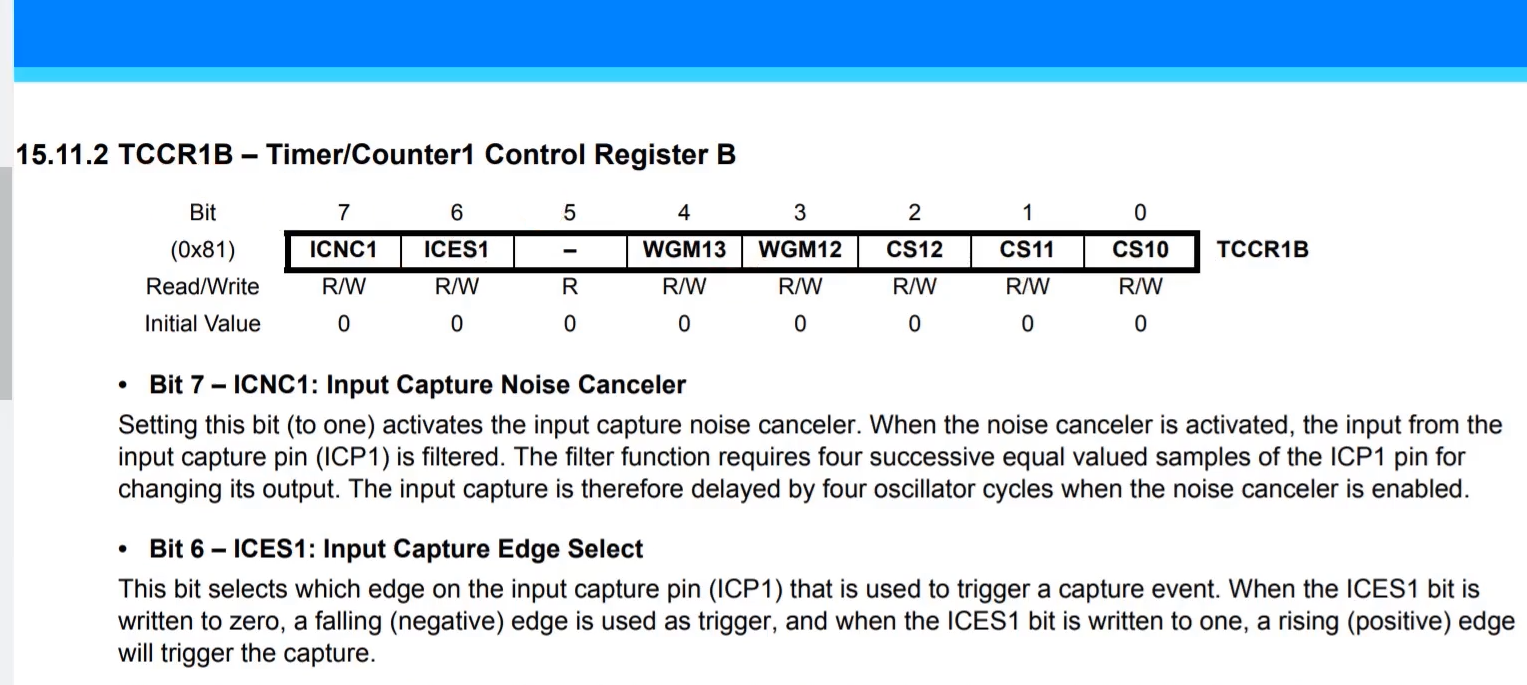
Here you can configure the Prescaler, and also, you should configure the WGM12 and WGM13 fields.
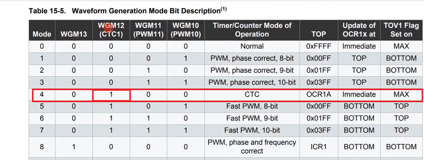
In the table, WGM12 must be 1.
So, WGM12 must be 1; WGM13 you keep as 0. And 7 and 6 bit fields are something to do with input capture. So, we are not using input capture; let’s keep these 2 bit fields as 0.
And after that, 0, 1, 2, bit fields are for clock selection. Let’s see clock selection bits.

By default, it will be 0. When it is 0? the Timer is disabled, or the Timer/Counter is stopped. If we want to stop the counter, then you have to make these bit fields as 0.
And you can also use these bit fields to select the Prescaler values. So, I will go with 256. That means the main clock we are going to divide, that is, the main clock is clkI/O, which we are going to divide by 256. So, we are slowing it down. CS12 has to be 1 here. We do that.
Look at Timer1_setup function, I write the register name TCCR1B, and I’m just making those 2 bits as 1 here. That’s it. I’m just storing the value in binary.
And after that, we have to enable the interrupt for the compare event. That you can do in this register. Let’s go to the register Timer/Counter1 Interrupt Mask Register, and we will be using the output compare register A.
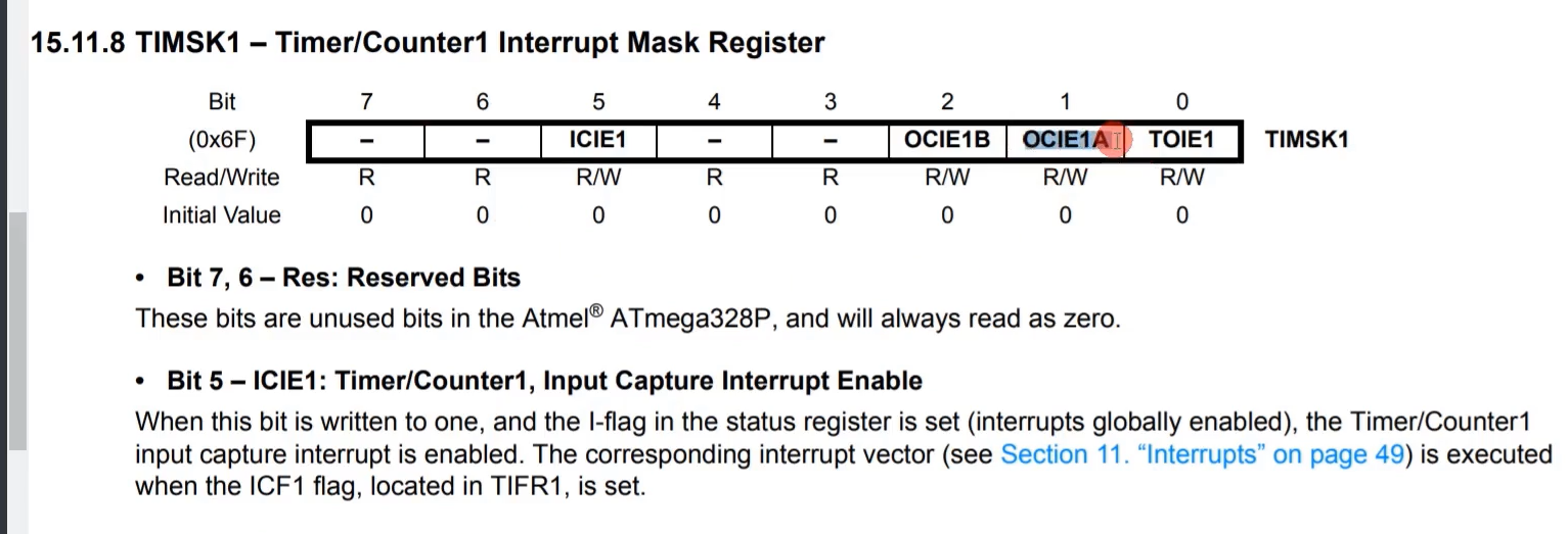
You have to enable this bit ‘OCIE1A’. IE means Interrupt Enable. Output compare interrupt enable for register A. You have to make this bit as 1. I do that TIMSK1 = B00000010;. And after that, keep the value in the OCR1A register. This is an output compare register A.
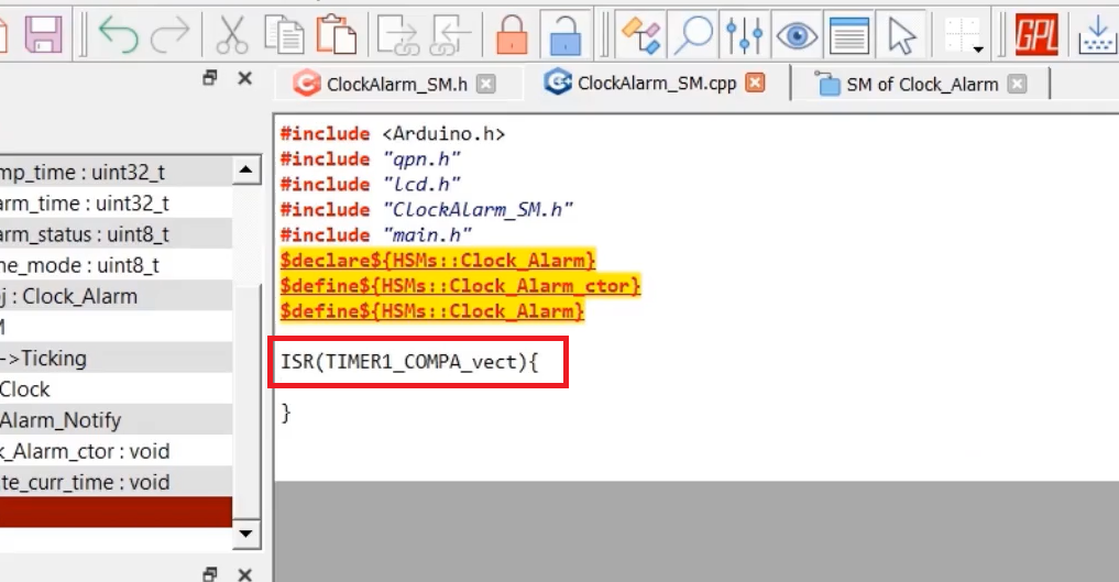
After that, go to the ClockAlarm_SM.cpp, and here we must implement the ISR. For that, use the ISR macro, and you have to give the vector address here (Figure 8).
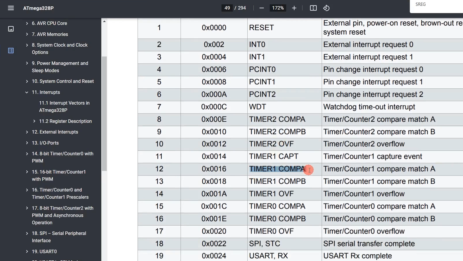
Vector address you can take from here(Figure 7) → Go to interrupts and interrupt vectors in this microcontroller, and ours is Timer Compare A.
Just select TIMER1 COMPA, and let’s go to the code and paste that. So, write TIMER1_COMPA_vect(Figure 8). That’s it.
Get the Embedded System Design using UML State Machines Full course on Here.
FastBit Embedded Brain Academy Courses
Click here: https://fastbitlab.com/course1

