Add the LVGL source code to an STM32 project
In this article, we will guide you on how to add the LVGL source code to an STM32 project and run sample applications on the STM32 board. We will start by covering the STM32F429 Discovery Board, which will serve as our primary board for demonstration purposes.
To begin, please visit the LVGL repository on GitHub. You will find that the LVGL project is already available for STM32F429, as well as other ST boards. If you navigate to the Repositories section, you will discover projects for boards such as STM32F769, STM32F746, and STM32H745.
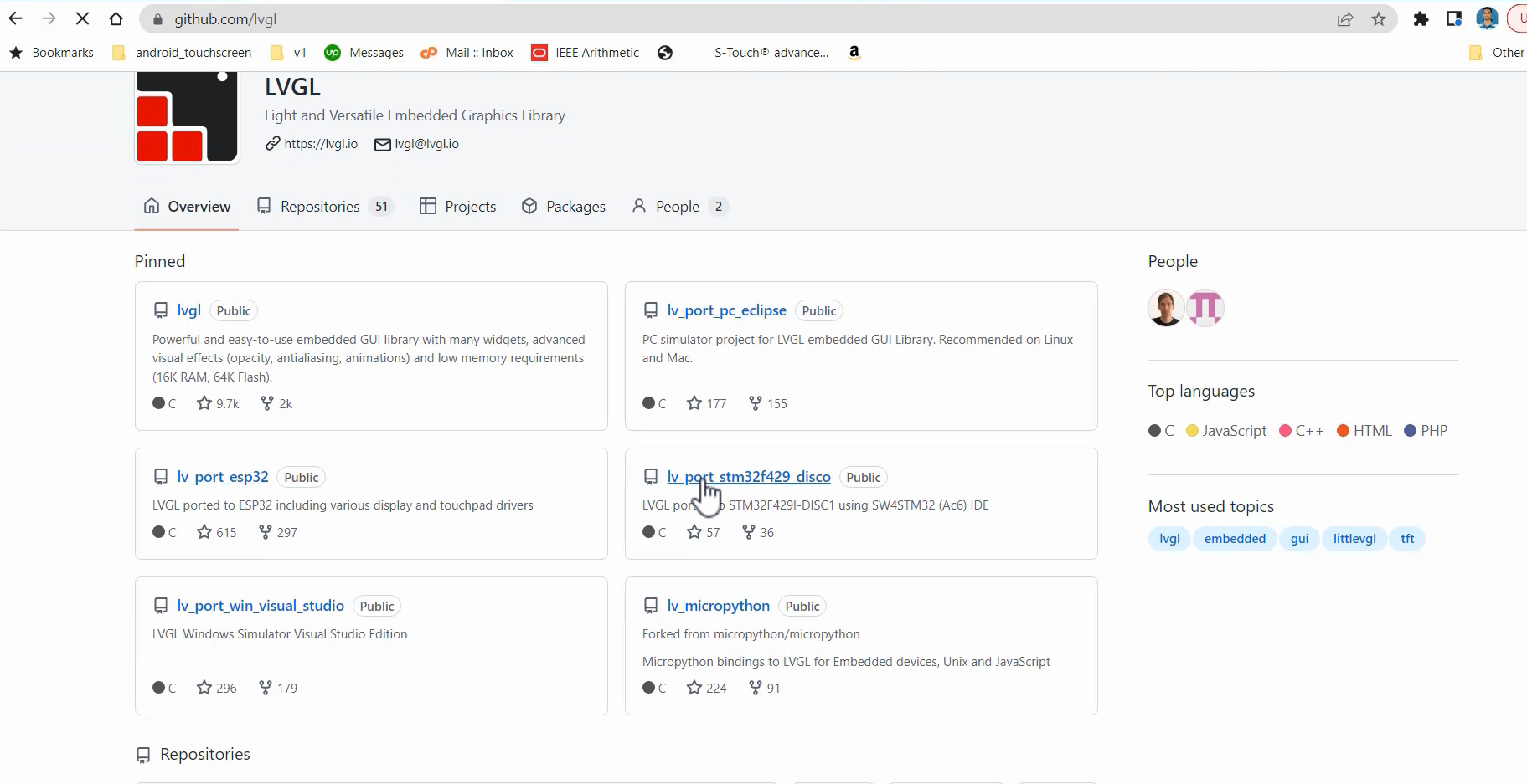
We will be using some files from the LVGL project. Therefore, you can simply download the project and run it without encountering any issues.
However, in this article, we are going to create an STM32Cube project. This is because, for our projects, we need to add and remove various peripherals, and we will be incorporating a significant amount of peripheral initialization code. This is why we choose to utilize the STM32CubeIDE’s auto code generation engine, which is a feature of STM32Cube.
Within the lv_port_stm32f429_disco project, you will come across the hal_stm_lvgl (Figure 2) folder, which contains the TFT driver files (Figure 3). These files include the LCD driver chip code and the driver for the touchpad, which is used by the touchscreen controller on this board.
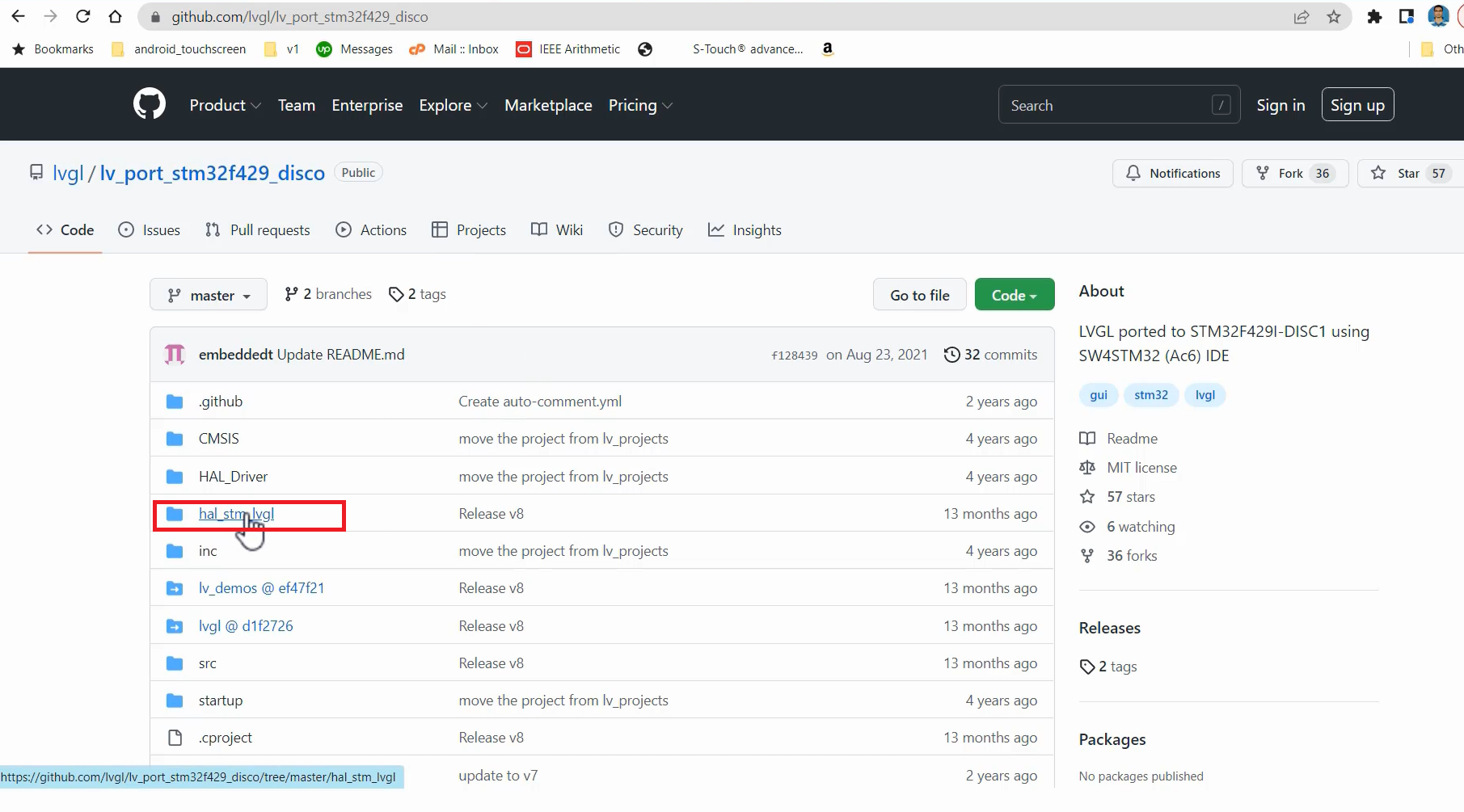
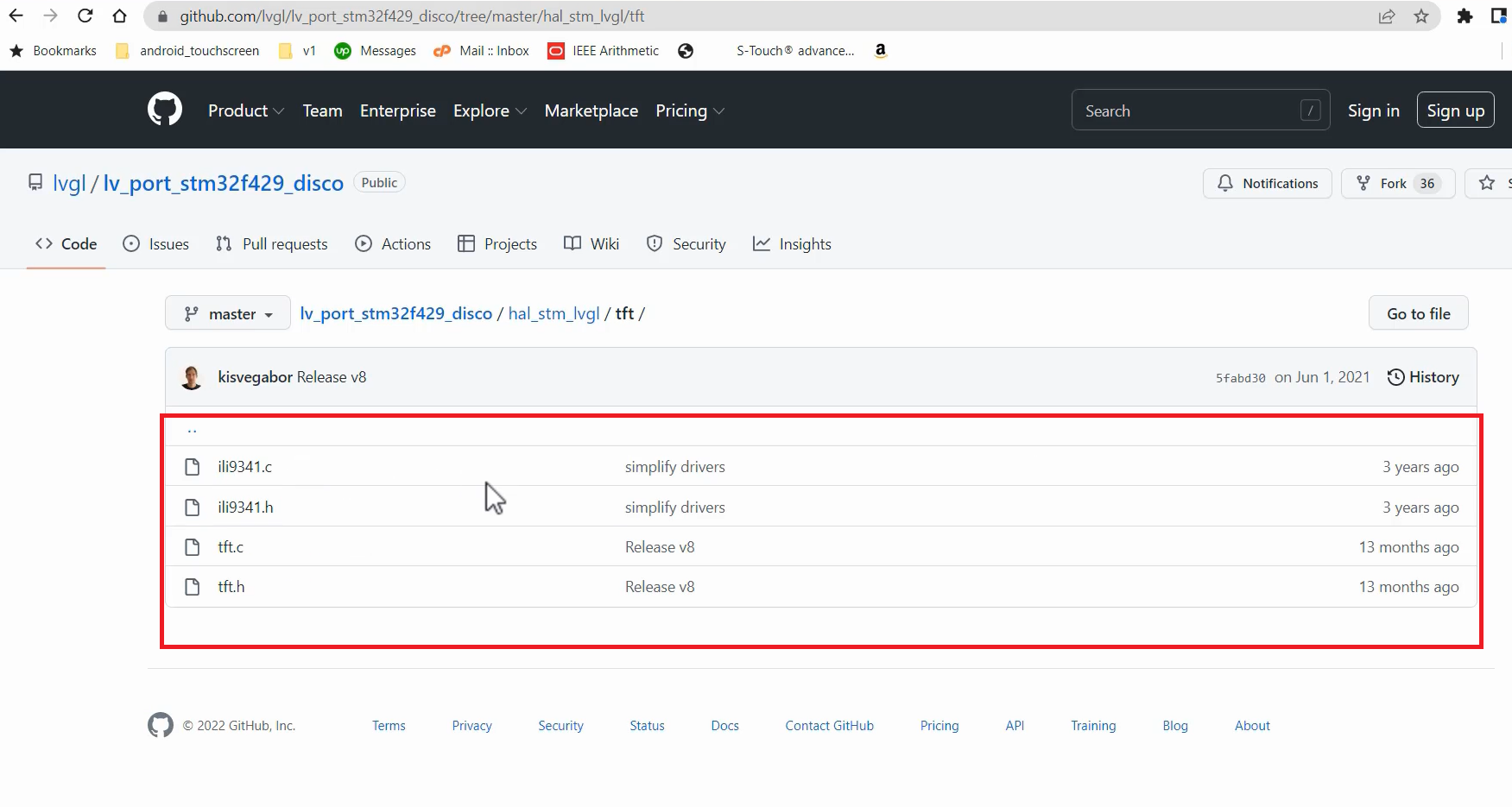
First, download this project onto your machine and save it in a convenient location. And then, we will create a new project using STM32CubeIDE, and we will use hal_stm_lv driver files.
For that, go to the lv_port_stm32f429_disco project, and you can clone it(Figure 4).
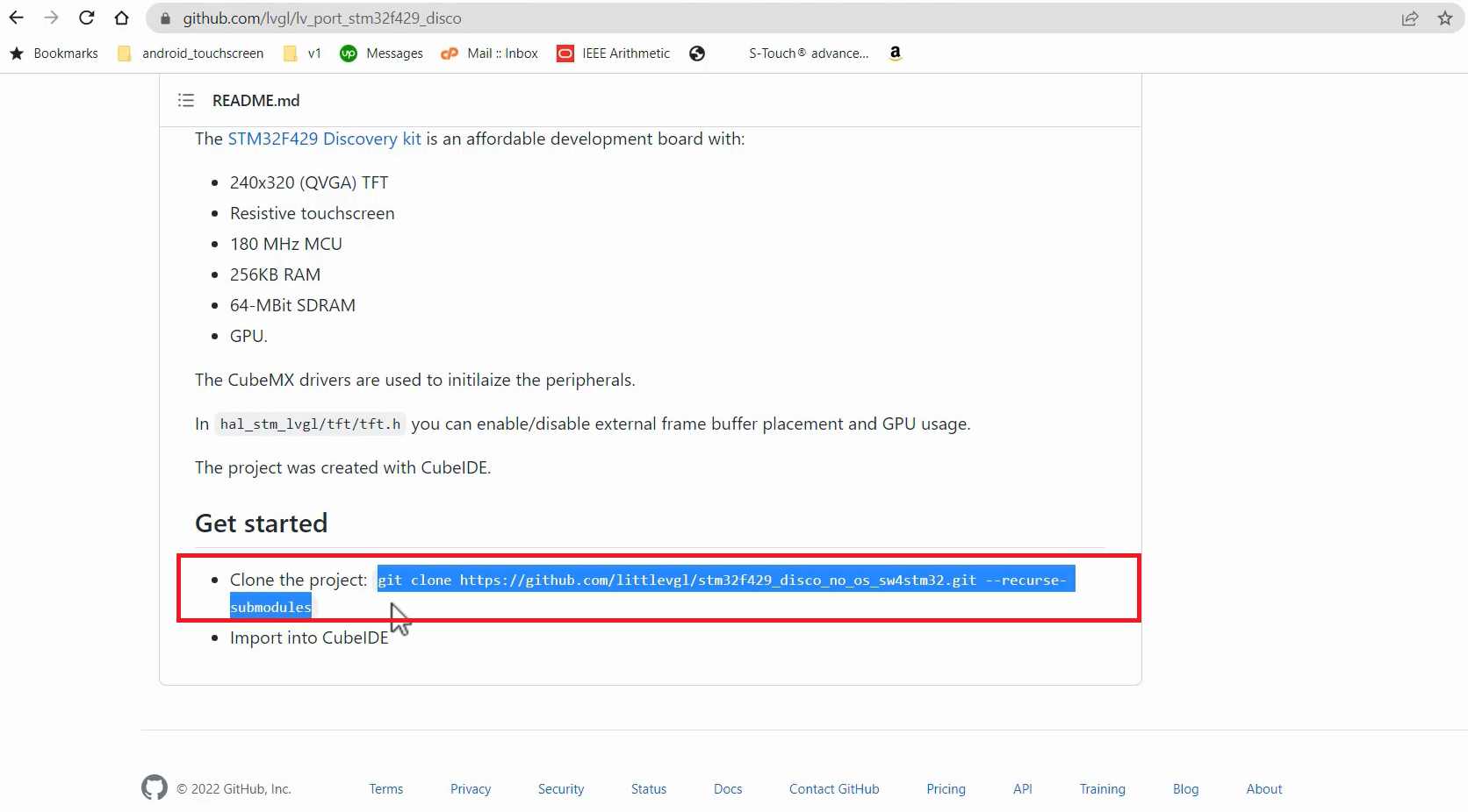
Just copy the git clone, and download this.
So, I cloned that project into my machine and can do it somewhere on your computer.
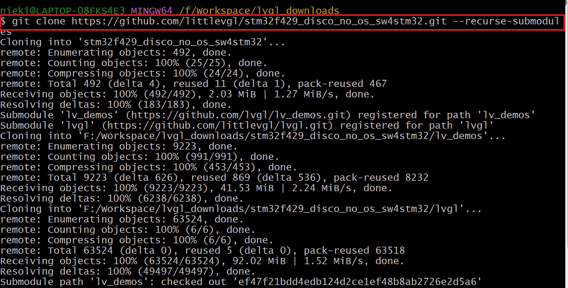
Next, return to the LVGL repository and clone the main LVGL code, which is found in the lvgl repository. We are particularly interested in the source folder. Clone this repository using the provided link. Note that now the lvgl.h file indicates the version as 8.3.0.
So, now let’s clone this.
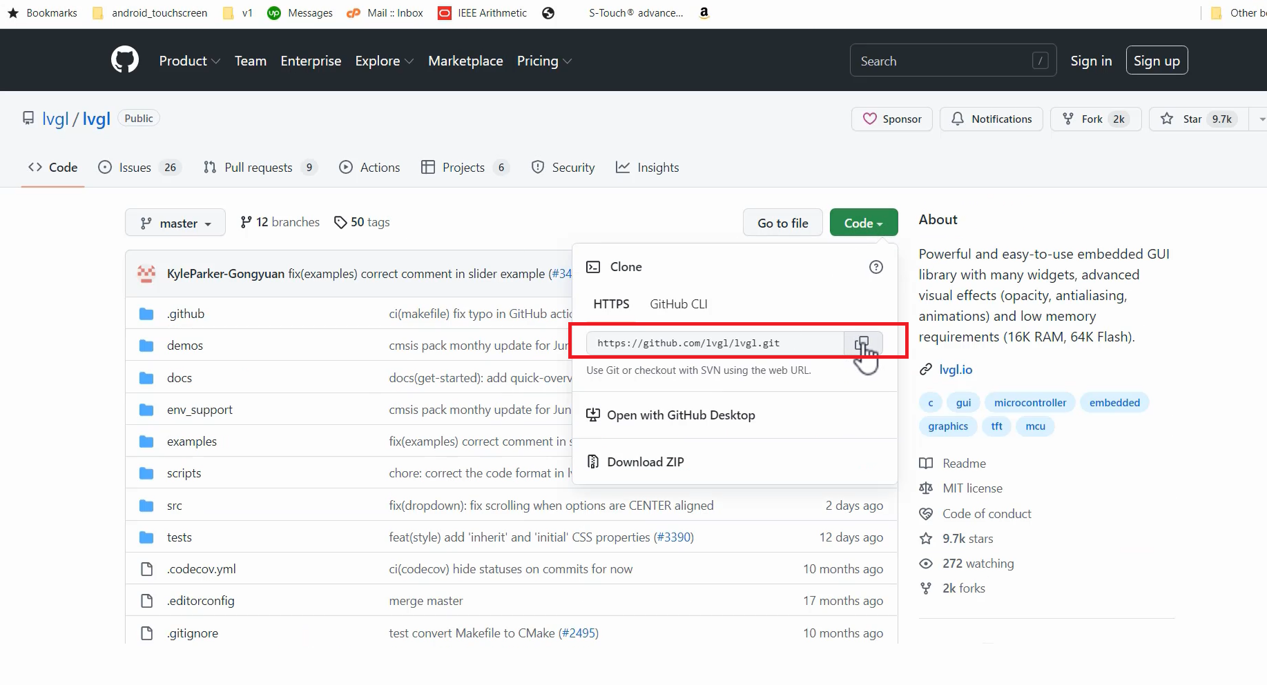
Just copy the main LVGL code and let’s do that(Figure 7).
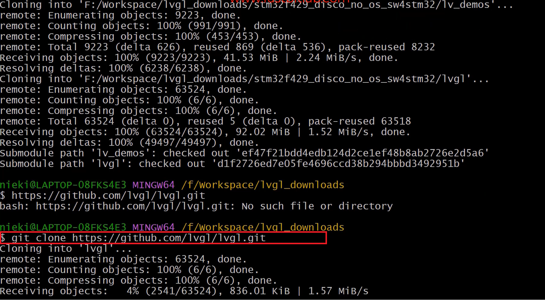
After that, let’s go to our STM32CubeIDE and create a new project. We are just trying out some examples from the LVGL repository in this project. Let’s create a new project first.
- Go to File → New → STM32 Project.
- In the Board Selector, enter the name of your board. For instance, I’m using the STM32F429I-DISC1 board. Select the appropriate board from the list and click Next (Figure 8).
- Provide a project name, select C as the targeted language, choose executable as the targeted binary type, and select STM32 project as the targeted project type. Click Next. Finally, click Finish (refer to Figure 9).


At this point, you will be prompted to initialize all peripherals with their default mode. Choose “No” for now.
The Device Configuration Editor will now open up. Click “Yes” to proceed (see Figure 10).

Please wait patiently as the editor initializes.
- Open your STM32CubeIDE project.
- In the Project Explorer view, expand the project folder.
- Look for a file with the extension “.ioc” (e.g., “your_project.ioc”). This is the Device Configuration File.
- Double-click on the “.ioc” file to open it in the Device Configuration Tool.
So, you already know what are the peripherals we need to use. We are using LTDC, SPI, and all initialization codes you can generate using this device configuration tool, which is a nice feature of this IDE.
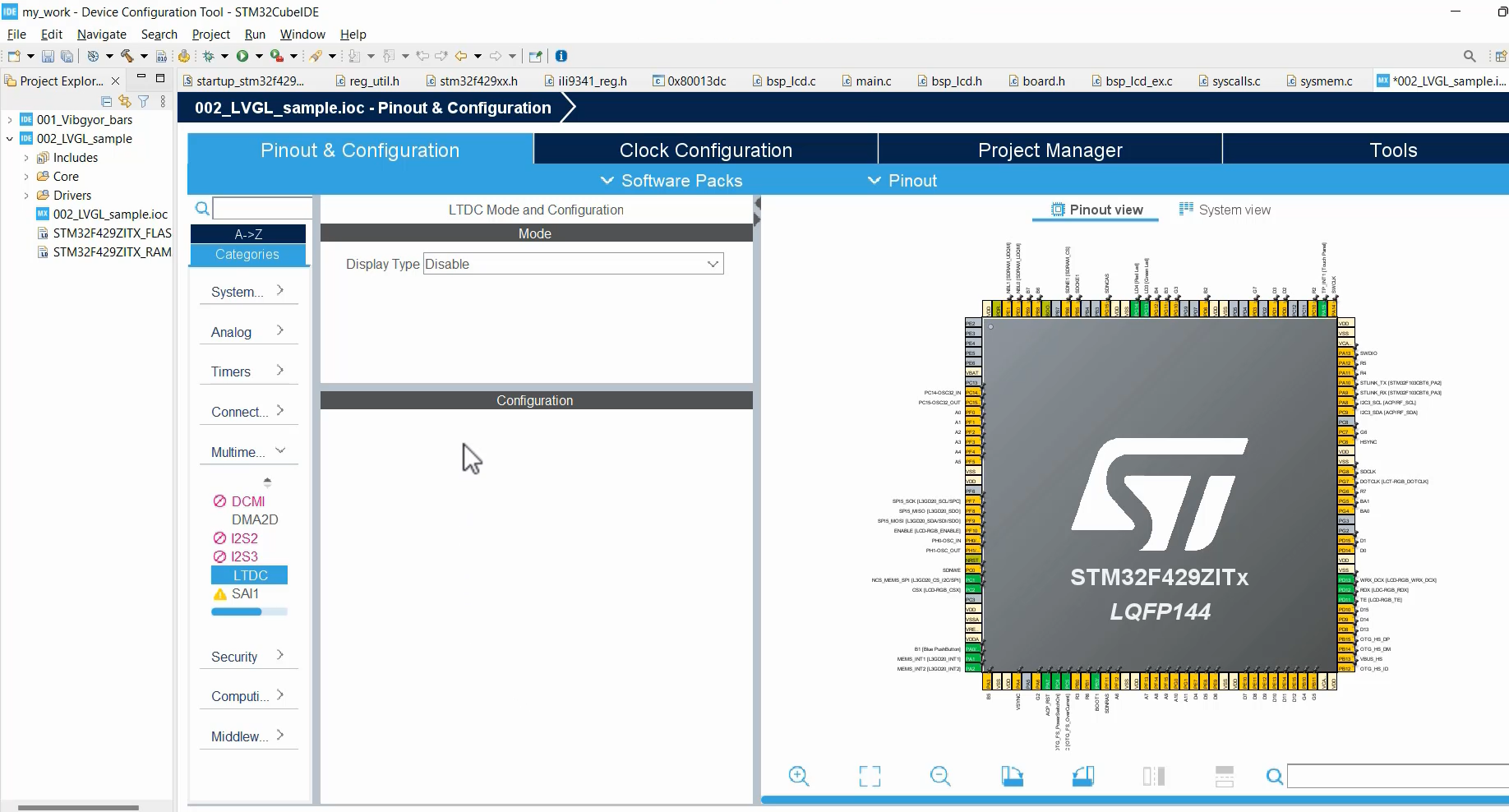
Now that you have a good understanding of LTDC (Layered Timing Display Controller) configurations, you can easily set up synchronization, timing details for SPI, and other configuration parameters. These options allow you to configure various aspects such as the display type, the number of layers, window position, pixel format, and timing parameters like HSW (Horizontal Synchronization Width), HBP (Horizontal Back Porch), active width, front porch, and back porch details.
However, for this specific project, we don’t need to make any such configurations. Therefore, I will keep these settings disabled for now, and I’ll explain why.
By keeping these configurations disabled, you don’t need to generate additional code using the STM32Cube Device Selector tool. Instead, you can simply activate the required peripherals. When you activate a peripheral, the corresponding driver for that peripheral will be automatically added to the project. Hence, you don’t need to perform any additional configurations.
For example, to activate the LTDC in STM32CubeIDE, follow these steps:
- Go to the “Multimedia” section in the Device Configuration Tool.
- Look for the LTDC option and select it.
- In the LTDC settings, you will need to specify the display type connected to the LTDC.
- Choose the appropriate display type from the available options. For example, if your display type is RGB666, select that.
By following these steps and activating the LTDC with the correct display type, you can proceed without performing any further configurations.
It’s important to note that this approach assumes that the default configuration of the LTDC and the connected display will work for your project. If you have specific requirements for synchronization, timings, pixel format, or other parameters, you may need to revisit the LTDC configuration and make the necessary adjustments.
However, if the default configuration is sufficient for your project, activating the LTDC with the correct display type should be enough to integrate it into your STM32CubeIDE project.
Similarly, go to Connectivity and enable SPI5, as we are using SPI for this project.
You can choose to enable Full-Duplex Master or Half-Duplex Master, depending on your specific requirements. No additional configuration settings are required here either because the LVGL’s tft.c file already handles that.
Next, let’s move on to the important aspect of clock configuration. We need to ensure that our system’s HCLK (High-Speed Clock) is set to the maximum value supported by the microcontroller, which in this case is 180 MHz. To achieve this, enter “180” in the appropriate field and press Enter.
The clock configuration tool will analyze the system requirements and attempt to find a suitable solution to achieve the desired 180 MHz HCLK frequency. If it successfully finds a suitable configuration, you can proceed with that. However, if it fails to find a suitable solution, you have the option to cancel and manually configure the values.
When manually configuring the clock values, it’s important to choose legal values that adhere to the specifications and limitations of the microcontroller. These legal values ensure proper functioning and stability of the system.
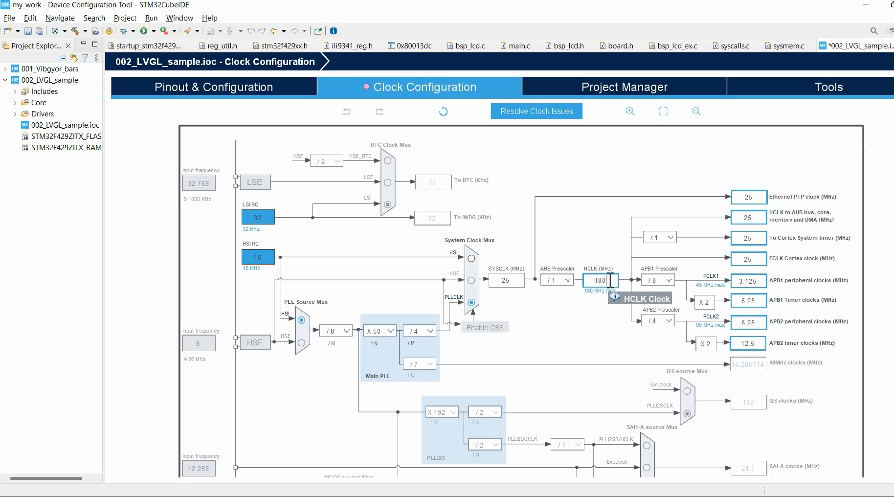
Take the time to carefully select the appropriate values for the clock configuration, considering factors such as the input clock source, PLL settings, and division factors. By choosing legal values, you can maintain the integrity and reliability of the system’s clock setup.
For example, if I select some wrong value here (some bad options), and you can see that it shows in Red, that means it’s not a legal value, as shown in Figure 13.
By paying attention to the color-coding and avoiding red-highlighted options, you can make sure that the selected clock values are valid and compatible with the microcontroller. This attention to detail helps maintain the integrity and proper functioning of the system’s clock setup.
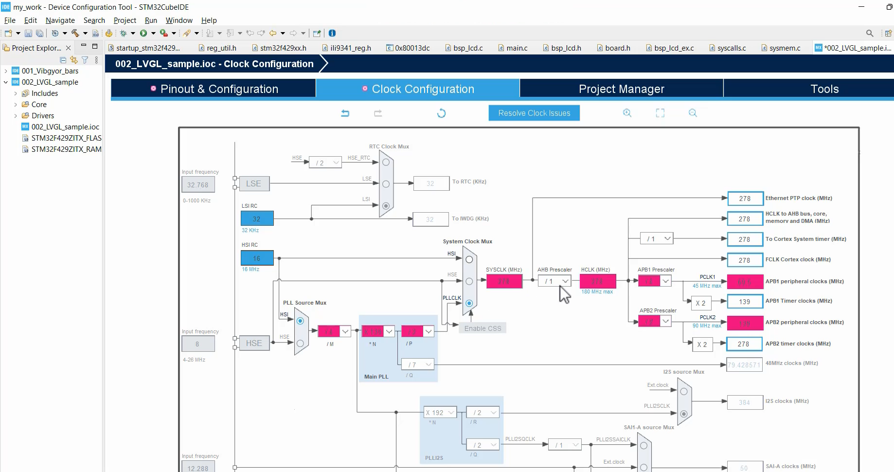
Once you have completed the clock configuration and finalized the settings, it’s time to save the configuration. Click on the appropriate option to save the settings.
After saving the configuration, STM32CubeIDE prompts you with the question, “Do you want to generate code?” Here, click on ‘Yes’ to proceed. The tool will then generate the necessary code based on the configured settings.
During the code generation process, STM32CubeIDE automatically adds all the required drivers to your project, including the LTDC driver as shown in Figure 14.
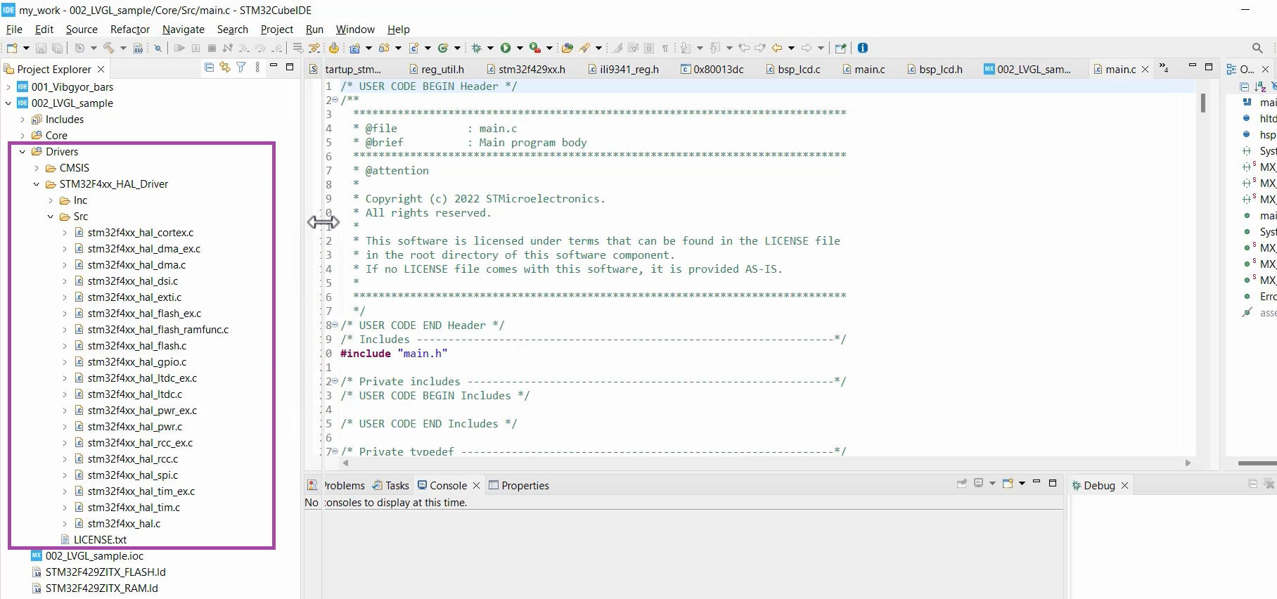
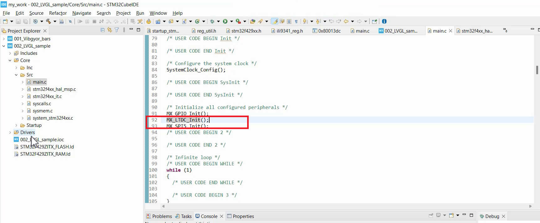
However, there is a small issue with this generated code. If you navigate to the main.c file, you will notice that it also includes the LTDC configuration code and SPI configuration code (Figure 15), which is not necessary for our project since we are obtaining those configurations from the LVGL repository.
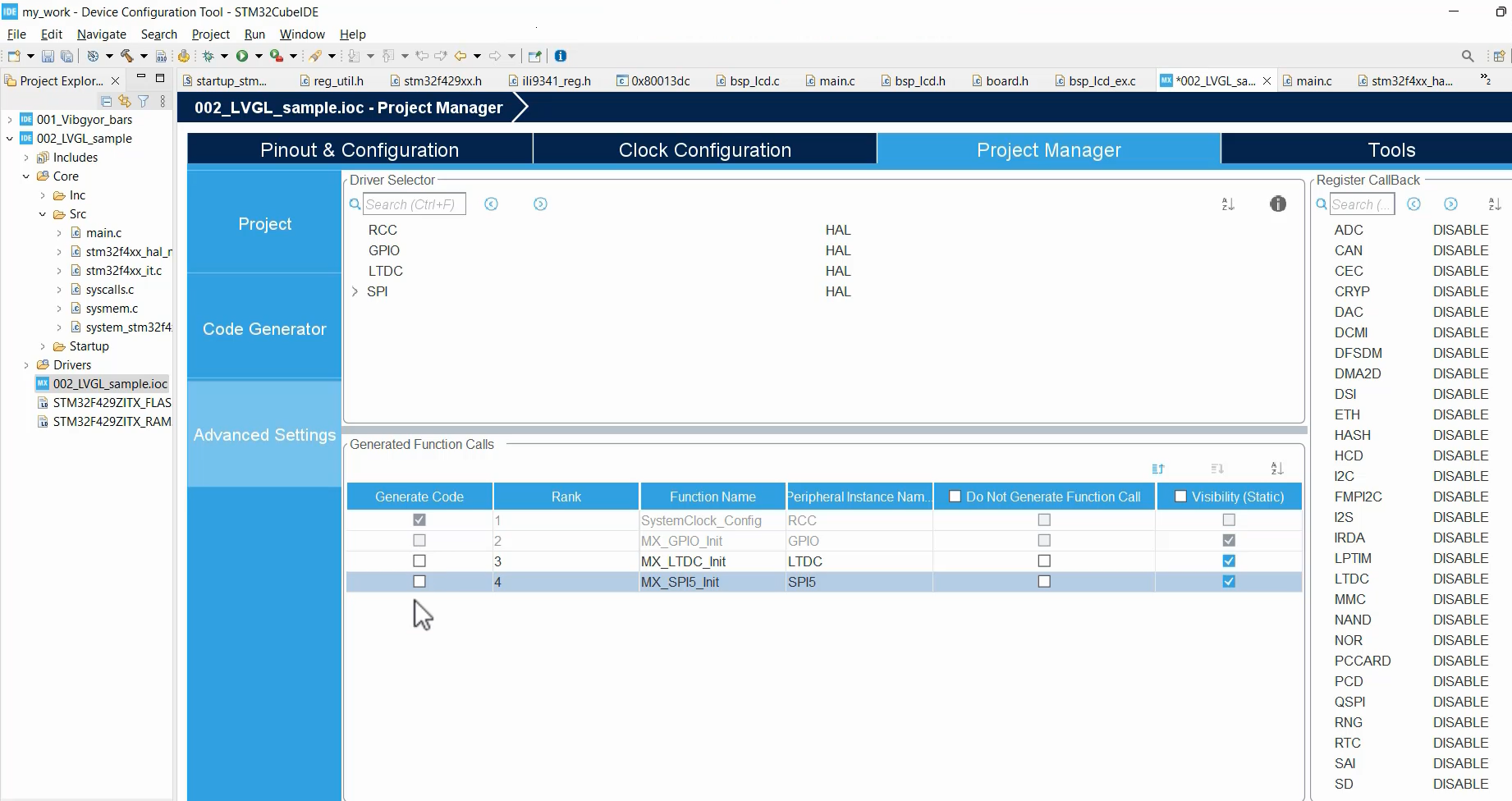
To resolve this, go back to the ‘.ioc’ file in STM32CubeIDE. Then, navigate to Project Manager, followed by Advanced Settings. Under Generate code, uncheck the following options: MX_LTDC_Init, MX_SPI5_Init, and MX_GPIO_Init, as shown in Figure 16. These configurations are not required since the LVGL file itself will handle the pin configurations.
Save the changes and generate the code once again. You will notice that the unnecessary function calls for LTDC and SPI configurations have disappeared from the main.c file. This ensures that only the essential LVGL-related code is included in your project.
By unchecking these options, you maintain consistency with the LVGL repository and prevent any potential conflicts or redundant configurations. Now, your code is streamlined and ready for further development with the LVGL integration.
Fastbit Embedded Brain Academy Courses
https://fastbitlab.com/course1

