Exercise-007 Clock Alarm Introduction
In this article, let’s do one more exercise. The exercise number is 007, and the exercise name is ClockAlarm. In this exercise, we will implement a real-time clock using the software. That means we are not using any RTC chip.
Requirements:
- Show current time of the day
- Clock setting
- Alarm setting
- Alarm notification
- Show Date, month, year, day of the week [TODO]
- Date setting[TODO]

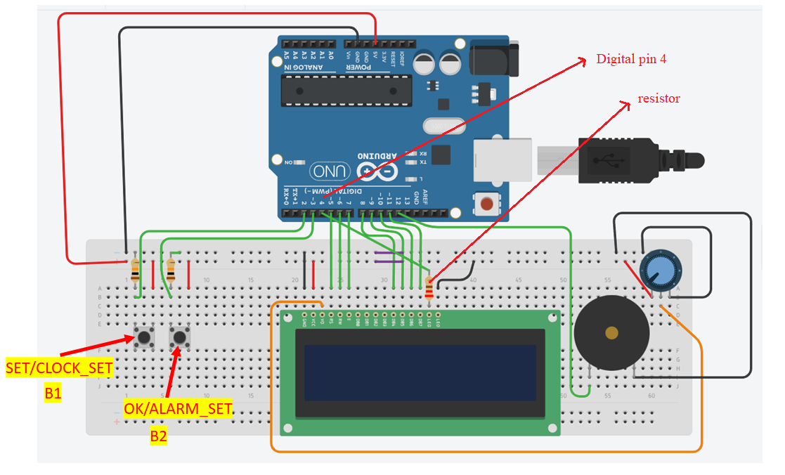
The circuit diagram of the 007ClockAlarm project is pretty much similar to the previous one.
There will be two buttons on the button pad.
- The first button is B1, a multi-functional button that can be used to SET and CLOCK_SET functionalities. If you want to execute SET functionality, you can use the B1 button. And to enter into the clock setting mode, you can use this button.
- The second button is B2, which is also a multi-functional button, and this is used for approval, which is ‘OK.’ If you have done some settings, you have to approve that, then you can use this button as OK. And this button can also be used to enter into the Alarm setting mode.
The digital pin 4 of the Arduino is connected to the LCD anode of the LCD backlight via this resistor. So, this is to control the backlight of the LCD, as shown in Figure 1. Compared to the previous circuit, those are just two changes in this circuit.
In the upcoming article, let’s see the demo of this application. So, that you get more idea of how the application looks like, you will come to know about other requirements of this project.
FastBit Embedded Brain Academy Courses
Click here: https://fastbitlab.com/course1


