Display interface types
Display interface types
There are 3 important interfacing types.
Interfacing means, interfacing the HOST controller and the Display module.
- MIPI DPI (Display pixel interface)
- MIPI DBI (Display bus interface/MCU interface)
- MIPI DSI (Display serial interface)
These are standardized by MIPI.
MIPI(Mobile Industry Processor Interface)
- MIPI Alliance develops interface specifications for mobile and mobile-influenced devices.
- In the mobile industry, companies use MIPI Alliance specifications when developing smartphones, tablets, laptops, and hybrid devices.
MIPI DPI
- This is also called as RGB interface.
- Applies to display interface which uses 16 or 18 or 24-bit data lines and control signals.
- The MIPI DPI specification standardizes the data and controls signals to be used by manufacturers of mobile device processors, cameras, and displays.
- The DPI interface is typically used when the display module doesn’t support the frame buffer(GRAM- graphics RAM). The Host controller must stream the data in real-time to the display.
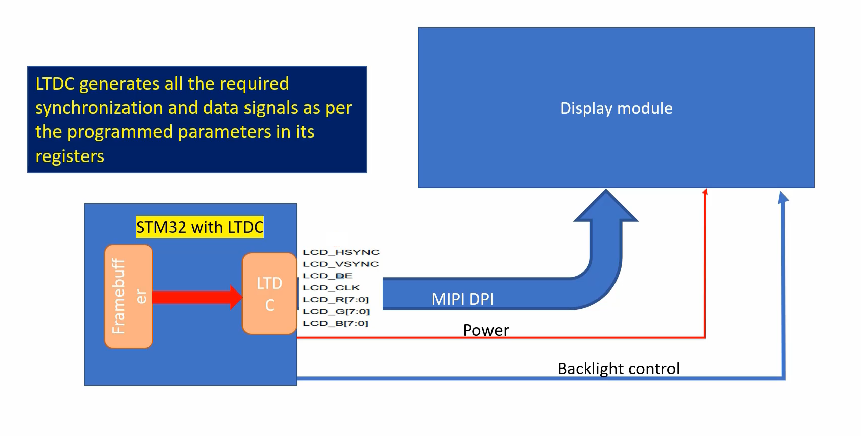
The MIPI DPI interface is shown in Figure 1, the signals of the MIPI DPI.
Whenever you see the control signals like Vsync, Hsync, data enable(DE), and Pixel clock (PCLK), along with the RGB data lines, you can say that this is MIPI DPI, also called as RGB interface. And these signals are controlled by the Host controller.
And the Host also must provide other signals like power signals and backlight control signals.
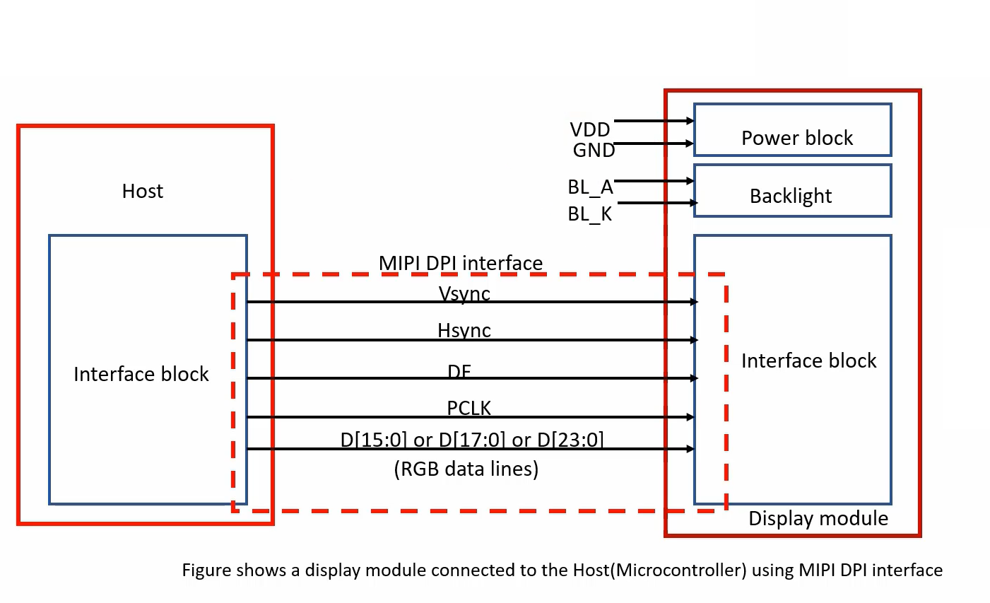
And please remember that as per the specification, The host processor interface must implement a 24-bit data width and accompanying control and timing signals. The host processor must be capable of transferring data as 16/18/24-bit words.
In our case, the host is LTDC. As you can see (Figure 2), the LTDC supports 24-bit data lines along with the timing and control signals. It knows how to control the signals and it can send data in 16 or 18 or 24-bit format. That’s why we can say that LTDC supports MIPI DPI.
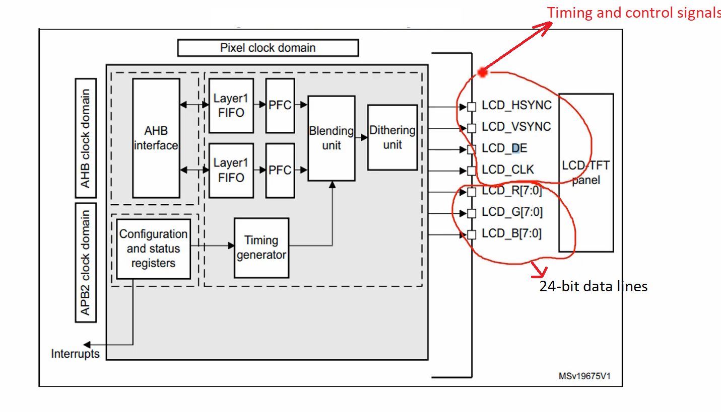
As per MIPI DPI display module need not to have the graphics RAM to hold the frame buffer.
And the display module interface must be implemented with a 16-bit or 18-bit or 24-bit data width.
In our case, we are using the ILI9341 LCD driver chip. It indeed supports a data width of 16-bit. It also supports a data width of 18-bit, but it doesn’t support 24-bit data width. But, that’s ok It should only support either one of these data widths.
Please note that all those control signals are controlled by the host(Figure 3).
MIPI DBI(Display Bus interface)
- Also known as MCU interface.
- The MIPI-DBI is used to interface with a display module with an integrated graphic RAM(GRAM). The pixel data is first updated in the local graphics RAM of the display driver chip which repeatedly refreshes the display.
- The host and display module can be connected by simple GPIOs.
- There are different types of MIPI-DBI. The first one is, DBI Type A.
- Types of MIPI-DBI are:
- DBI Type A: based on Motorola 6800 bus
- 8/9/16/18/24 bit parallel data transition is possible
- DBI Type B: based on Intel® 8080 bus
- 8/9/16/18/24 bit parallel data transition is possible
- DBI Type C: based on SPI protocol
- 3 or 4-line SPI interface
- DBI Type A: based on Motorola 6800 bus
Summary
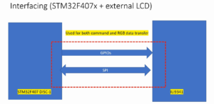
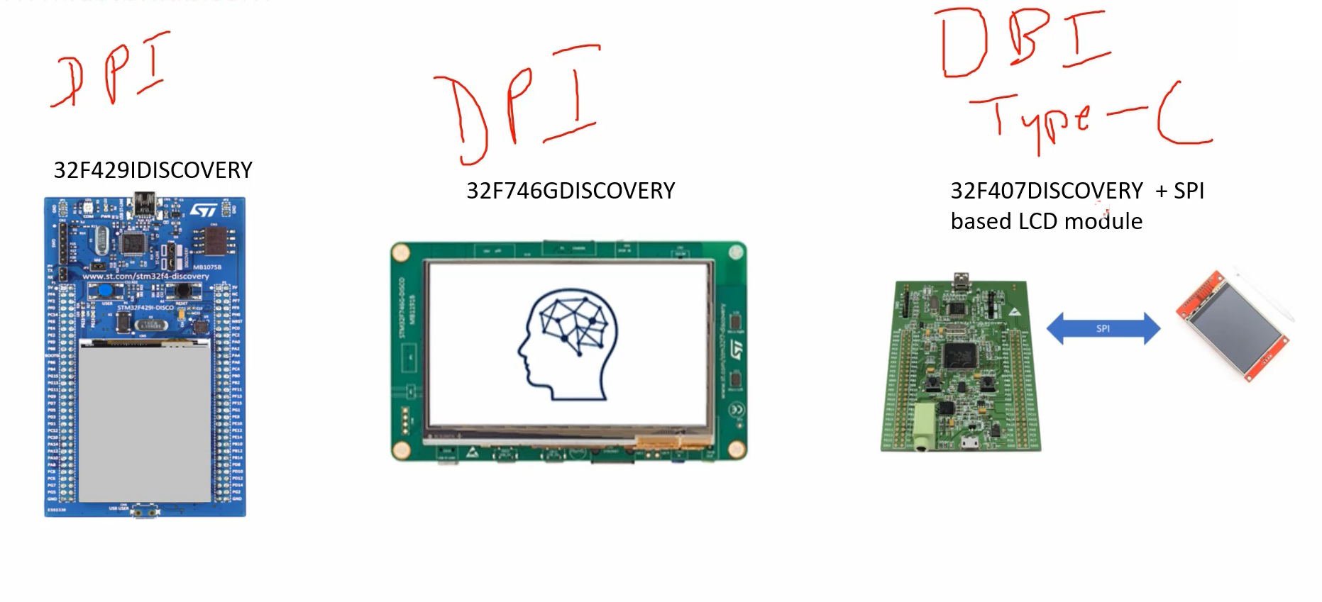
Here in the STM32F4IDISCOVERY board, we are using MIPI DPI. In the STM32F746GDISCOVERY board here also we are using MIPI DPI, but in STM32F407DISCOVERY+SPI based LCD module we are using DBI Type C. That is serial communication using SPI.
What is a DBI type A and DBI type B?
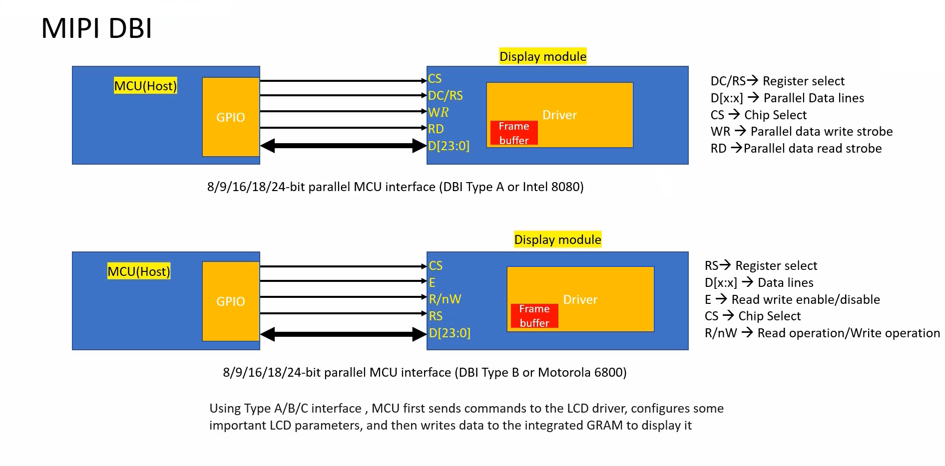
Look at Figure 5, these are just parallel data communication using some data lines. There could be 8, 9, 16, 18, or 24 data lines. There will be a graphics RAM or frame buffer in the driver chip itself.
The microcontroller whenever it wants to send data, it can send that data over the D[23:0] data lines and the data will then get transferred to the internal graphics RAM, and the driver chip will read from that graphics RAM and it updates the display. It works like that.
The remaining data line will define how to send the data, when to send the data, when to read the data, etc. Actually, you have to check the driver’s datasheet to understand the timing diagrams. I mean, when to assert DC, when to assert write strobe, read strobe, etc.
4 Line DBI serial interface
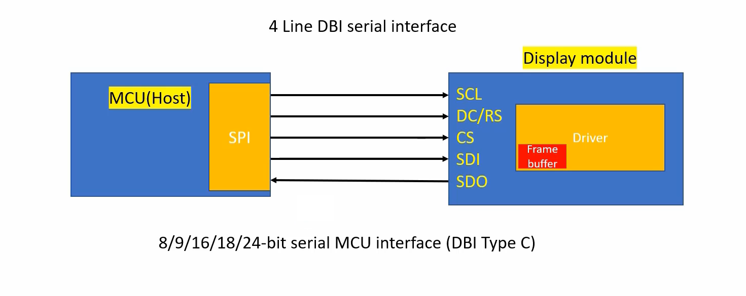
In 4 line DBI serial interface, SDI and SDO are data lines, it is considered as 1 line. SCL is a second line, which is a serial clock. And DC/RS and CS(chip select) these two are control signals.
Chip select(CS) is a third line. And DC/RS is a fourth line. This is to distinguish between data and command.
That’s why, it is called a 4-line DBI serial interface.
Actually, SDI means MOSI. SDO means MISO. So, the SDO arrow direction should be opposite of the SDI direction. SDO pin is required only if you want to read from the display module. If you want to read the contents of some registers or to read the contents of the graphics RAM. Otherwise, it is just considered a 4 line DBI Interface.
In the following article, we will understand the significance of RGB interface signals. Like Vsync, Hsync, data enable(DE), and DOTCLK.
Get Mastering Microcontroller: STM32-LTDC, LCD-TFT, LVGL (MCU3) Full Course on Here.
FastBit Embedded Brain Academy Courses
Click here: https://fastbitlab.com/course1

