Hierarchical State Machines(HSMs)
This article teaches about HSMs, which stands for Hierarchical state machines.
In the previous article, we used the Flat state machine(FSM) approach for our project. A flat state machine means there were no composite states. You don’t see any state embedded within another state. The state machine diagram had a couple of states interconnected by a couple of arrows here. So those are nothing but the external transition, and the state machine diagram looks messy, as shown in Figure 1.
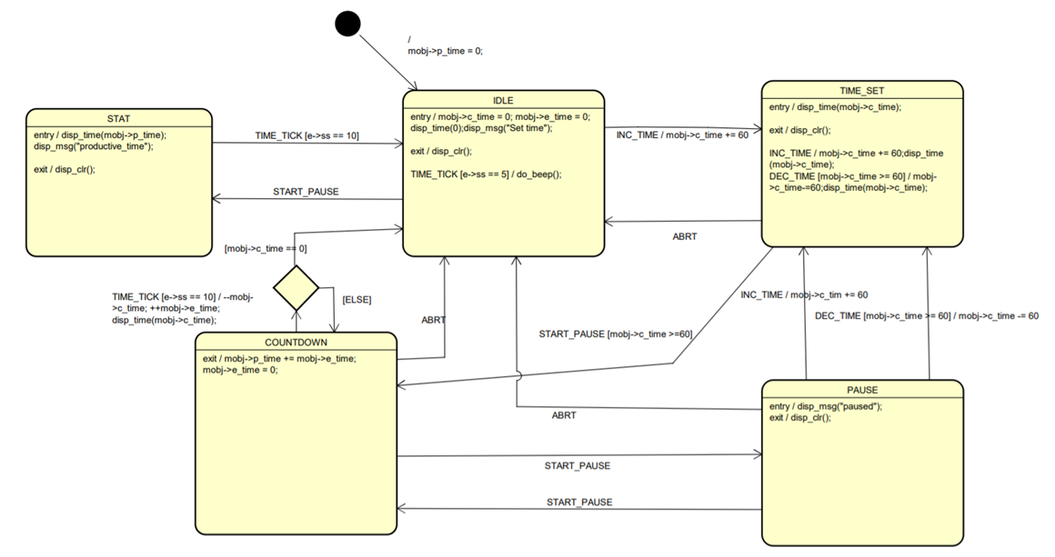
For this exercise, there were just five states. So, it was quite manageable. But when you want to introduce more features to your application, you could be introducing more states. And when you introduce more states, obviously there will be many transitions among the states, more Guard conditions, so drawing your state machine gets complicated.
When the complexity of the state machine diagram increases, it becomes too tedious to maintain, visualize, and troubleshoot. That’s why it would be better to explore what are hierarchical state machines used to tackle this problem.
HSMs will greatly reduce the complexity introduced by the Flat state machine approach.
Disadvantages of using a Flat state machine
- As the number of states increases, the number of transitions tends to increase, which increases the complexity
- Hard to draw, visualize, trace and troubleshoot
- Chances of committing more mistakes by missing transitions
- Code repetitions (not efficient code reusability)
Hierarchical State Machines(HSMs)
The word ‘Hierarchy’ we observe in our day to day life.
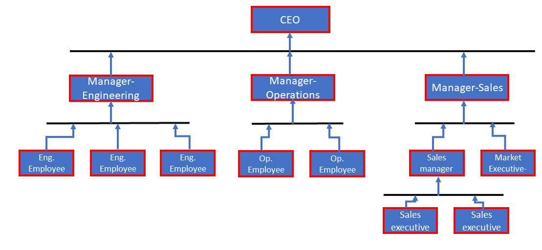
For example, consider the hierarchy of what you find in the corporate world. There is a strict hierarchy in the company, under which all the employees work, and the company operates with a strict hierarchy. There will be a CEO of the company; under the CEO, there could be a couple of VPs and managers, and under each manager, there will be a team of Engineers, etc. This is a hierarchy.
For the states also, you can draw such a hierarchy, as shown in Figure 3.
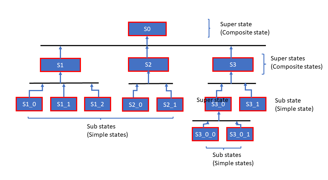
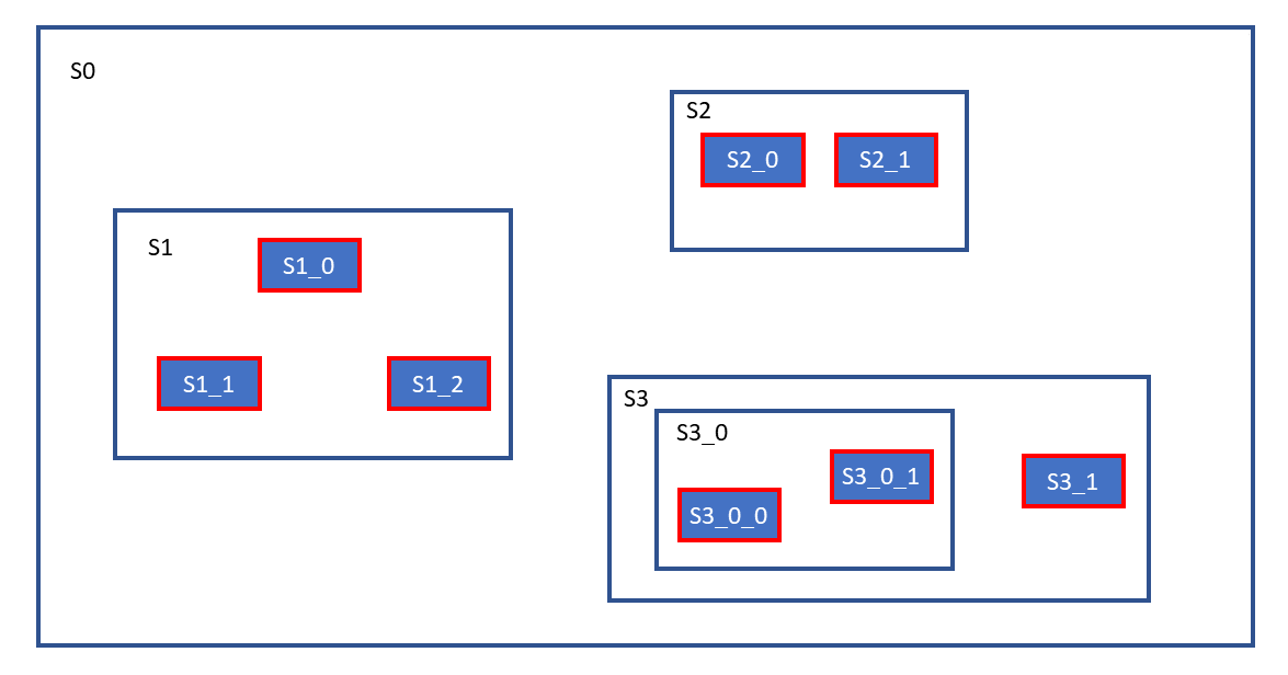
For example, consider a picture shown in Figure 4. S1_0, S1_1, S1_2 are states or substates or child states of S1 (super state), which can be introduced like this shown in Figure 3. There is a state S1, and under which there could be a couple of substates, like that.
Here, S1_0, S1_1, S1_2 can be called a direct substate of S1, or S1 can be called a direct super state of S1_0, S1_1, S1_2 substates. S1 also can be called a simple composite state. And S1, S2, and S3 are direct substates of the superstate S0, and like that. Here, S1_0 is not a direct substate of S0; you can call it an indirect substate of S0.
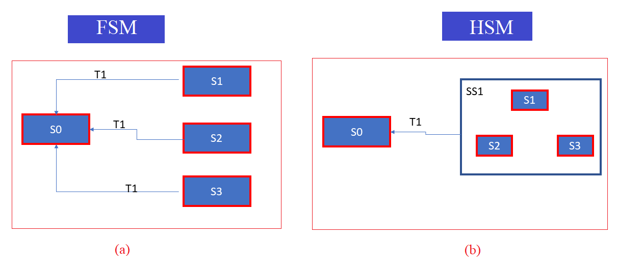
Hierarchy’s can be of any level. Consider this example, shown in figure 5 . There are three states; S1, S2, and S3. And all these have common behavior. And the common behavior is whenever the trigger T1 happens, and the application state moves from one state to another.
For example, look at picture (a). Currently, the application state is S2, when the trigger T1 happens, the application state moves from S2 to S0, that’s an external transition. And this behavior is common among S1, S2, S3 states. That’s why it could hint that we can transform this state machine diagram(a) into this one(b) using a hierarchical approach.
In picture (b), SS1 is a composite state or a superstate consisting of 3 substates; S1, S2, and S3. And it inherits the common behavior of these three states to itself.
When the application is in the S1 state when trigger T1 happens, the meaning of this diagram is(b), S1 doesn’t handle T1. That’s why the trigger propagates to its superstate, that is, SS1. And SS1 handles it, and there is a transition to S0. That’s the meaning of this state machine diagram. The same thing is applied to S2, S3 states as well.
When the application state is in S2, and when T1 happens, S2 doesn’t handle T1. Hence, it propagates to its superstate and SS1 handles it, and the state moves to S0.
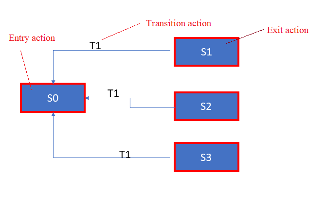
And here, what’s the sequence of execution when T1 happens? The application is in state S1, and T1 happens; what’s an execution sequence as per the UML specification? First, the exit action of S1 will be executed, then the transition action T1 will be executed, and lastly, the entry action of an S0 will be executed. That’s a sequence.
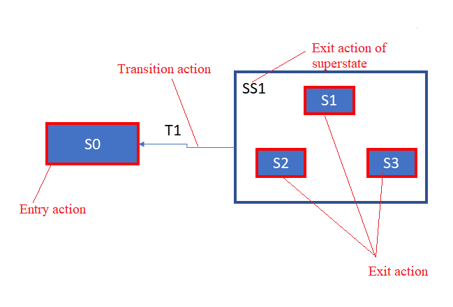
The same thing should be applied to here as well, as shown in Figure 7. When the state is S3, and when T1 happens, the T1 propagates to the superstate(SS1), superstate handles that trigger T1, and there will be an external transition.
When that transition happens,
- Exit action of S3 will be executed.
- And then, exit action of SS1 superstate will be executed if it is defined, because in this case, when T1 triggers, the superstate S11 is also exited. As per the UML specification, when the superstate is exited, the exit actions must be executed from the innermost leaving state towards the outermost state.
- And after that, the transition action will be executed
- Then, the entry action of the new state S0 will be executed.
The advantage is, in HSM, the complexity is reduced. And also, you can control code repetitions.
For example, in the Flat State Machine (see figure 5), the transition action T1 has to be mentioned in three places. But in HSM, you have to mention the transition action T1 in one place. So, one place means there is only one point of control; at only one place, you have to modify something if you wish to do so. That’s why HSM helps you to reduce code repetitions. We will learn more about HSMs with code examples in the upcoming articles.
Get the Full Course on Embedded System Design using UML State Machines Here.
FastBit Embedded Brain Academy Courses
Click here: https://fastbitlab.com/course1