Exercise: I2C slave programming
Exercise:
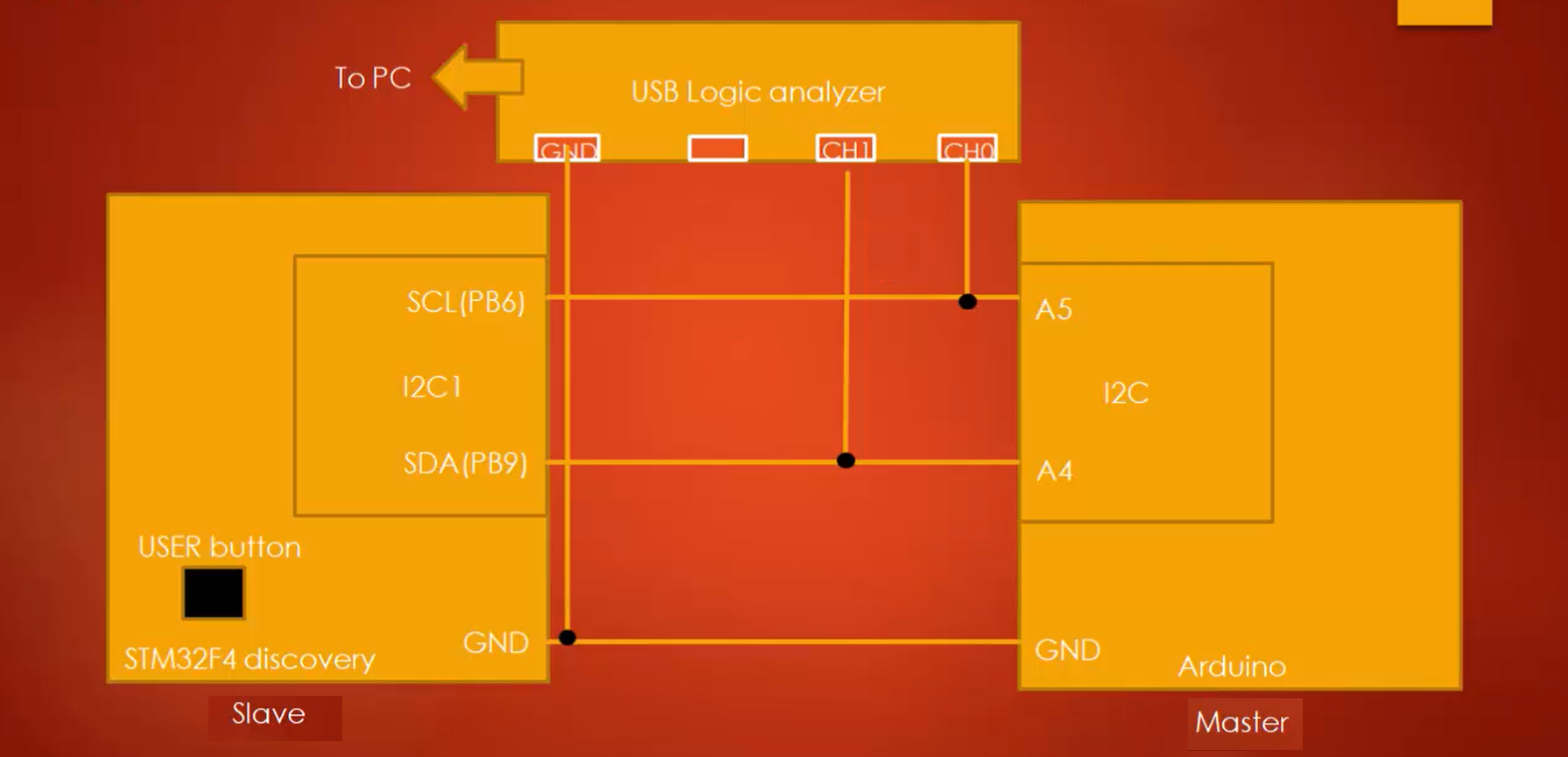
Now let’s do one exercise where the STM32 is the I2C slave, and the Arduino board is the I2C master. The master should read and display data from the STM32 slave connected. First, the master has to get the length of the data from the slave to read subsequent data from the slave.
- Use I2C SCL = 100KHz (Standard mode)
- Use internal pull resistors for SDA and SCL lines.
The exercise is exactly the same as the previous one, but the difference is now the STM32 is a slave and Arduino is a master.
Things required to do the exercise:
- Arduino board
- ST board
- Some jumper wires
- Bread board
- 2 pull-up resistors of value 4.7KΩ (only if you are in doesn’t support internal pull up resistors).
The connections for this exercise are as shown in Figure 1 and Figure 2.

Steps:
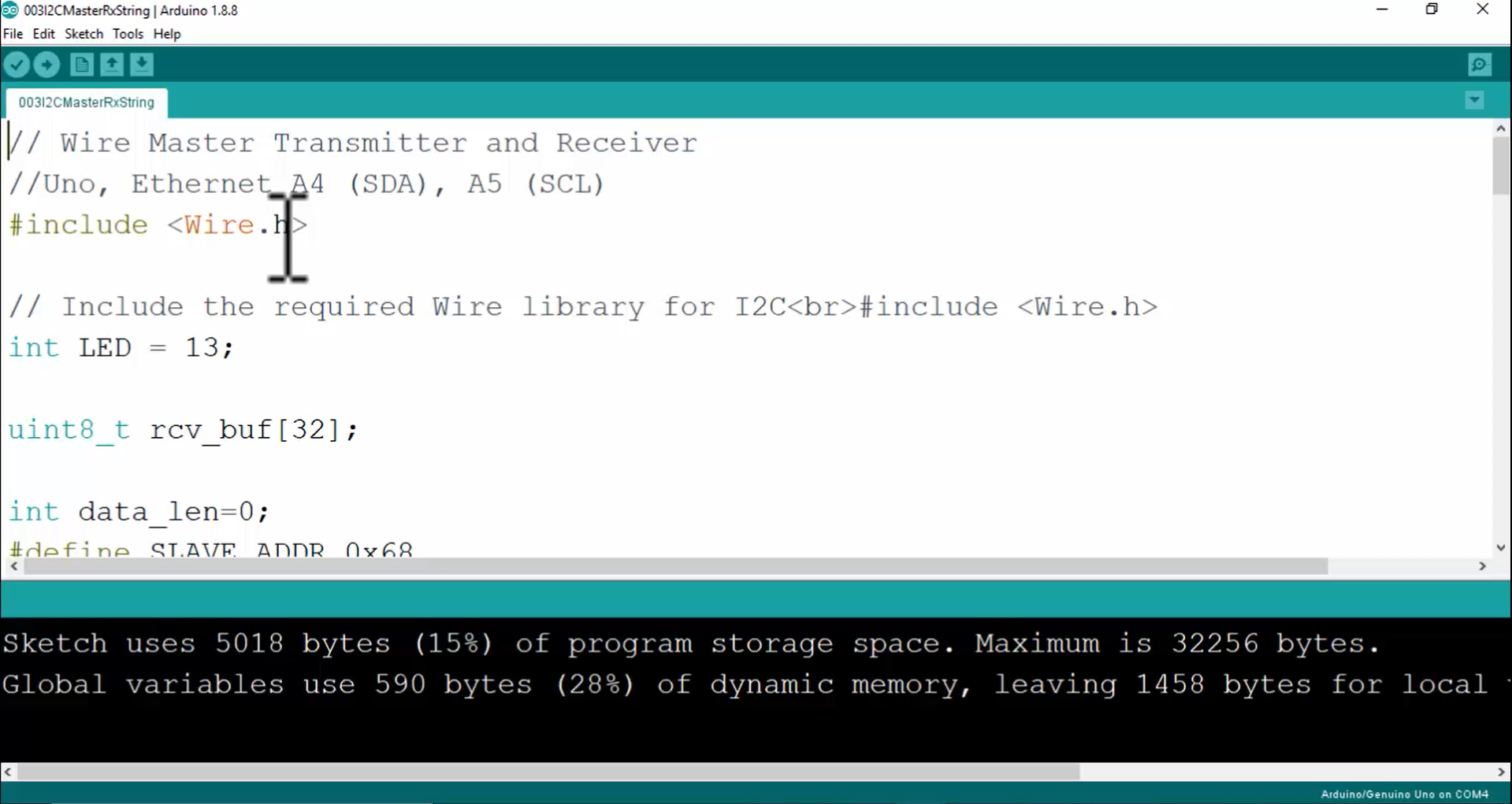
1. Make the connections, as shown in Figure 2. First, the transaction will be initiated from the Arduino board. Power your Arduino board and download the I2C slave sketch to Arduino, and the name of the sketch is 003I2CMasterRxString.ino (Figure 3).
2.Download the code into the Arduino by clicking on the upload button.
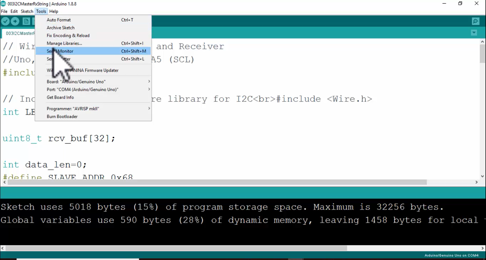
3. Go to the tools and open the serial monitor (Figure 4).
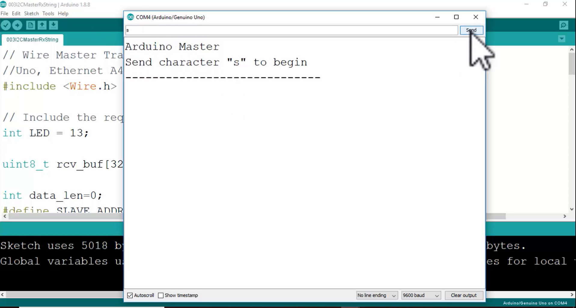
4. Now the serial monitor is opened (Figure 5). On the serial monitor, it is printed that “Send character “s” to begin”. So, in order to trigger the I2C transactions with the slave, you have to type lowercase s on the serial monitor, and then you have to send it.
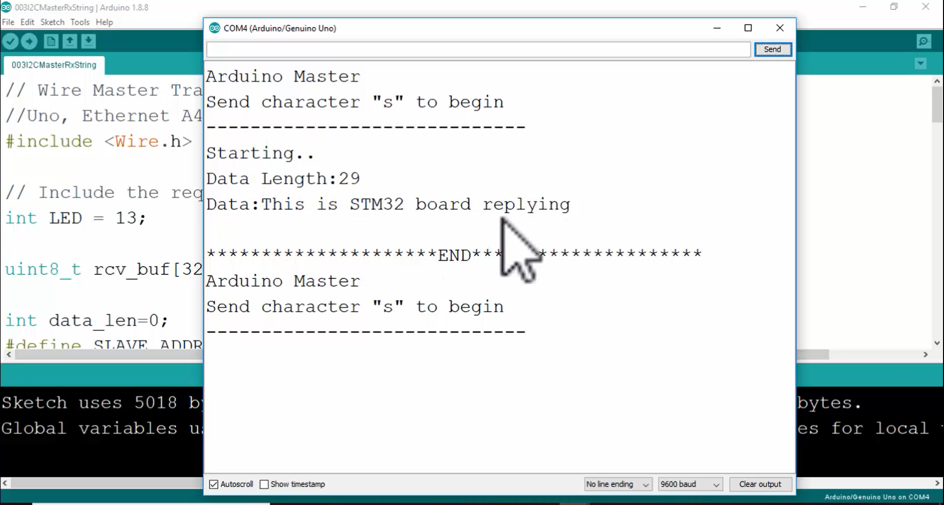
5. The STM32 slave will receive the I2C transactions generated by the master, and it will reply to the master, and then the master is going to display the message received on the serial port, as shown in Figure 6.
All the I2C transactions are the same. There is no change in the I2C transactions. In I2C transactions to read the 1-byte length information from the slave, all the transactions shown in Figure 7 and Figure 8 are now generated by the Arduino board instead of the STM board. All the transactions are now triggered by the master, and the STM slave should respond to these I2C transactions.