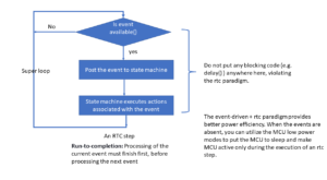
Exercise: Coding Part 1
Now let’s implement the I2C slave exercise.
Steps of implementation:
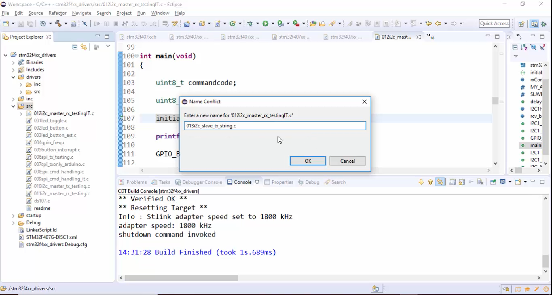
- Create the new source file: Copy the old source file and paste it in the src section. Then change the name to 013i2c_slave_tx_string.c, as shown in Figure 1.
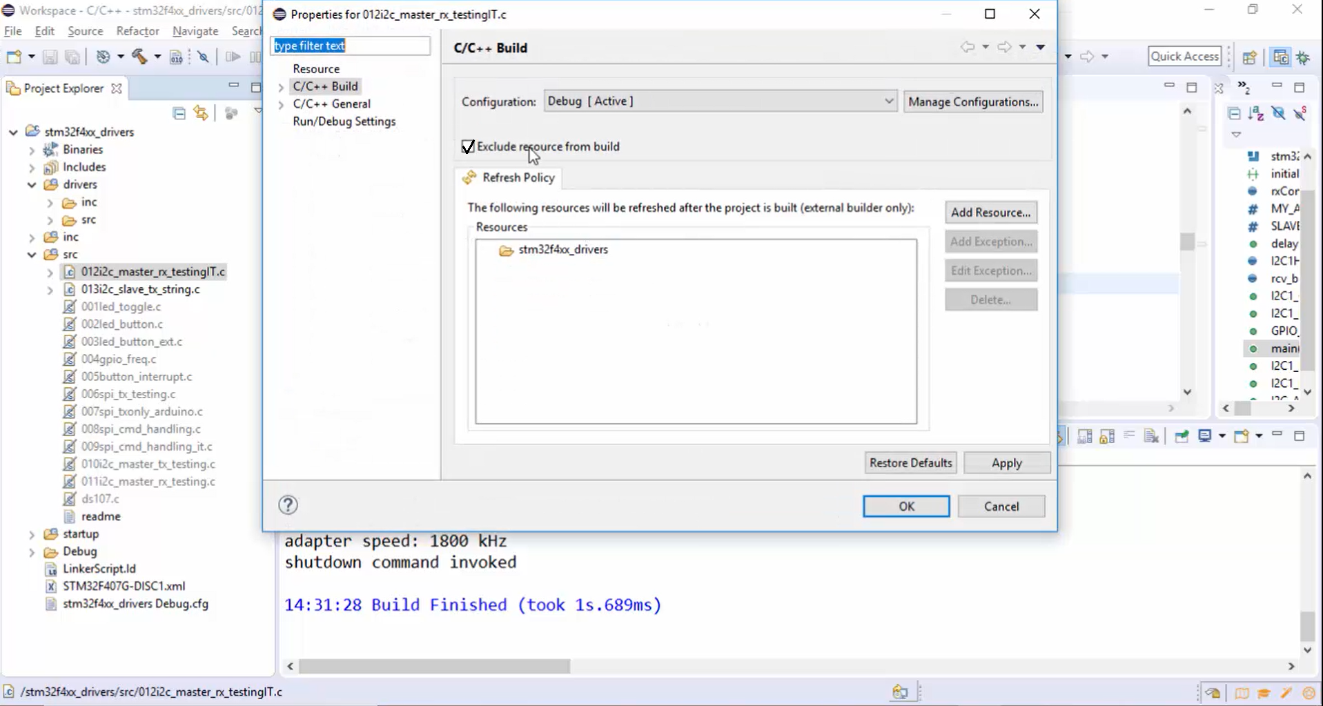
2. Exclude the old file from the build (Figure 2).
3. Now let’s modify this code according to the need of our exercise.
a. First, remove all the semi hosting related codes shown in Figure 3.

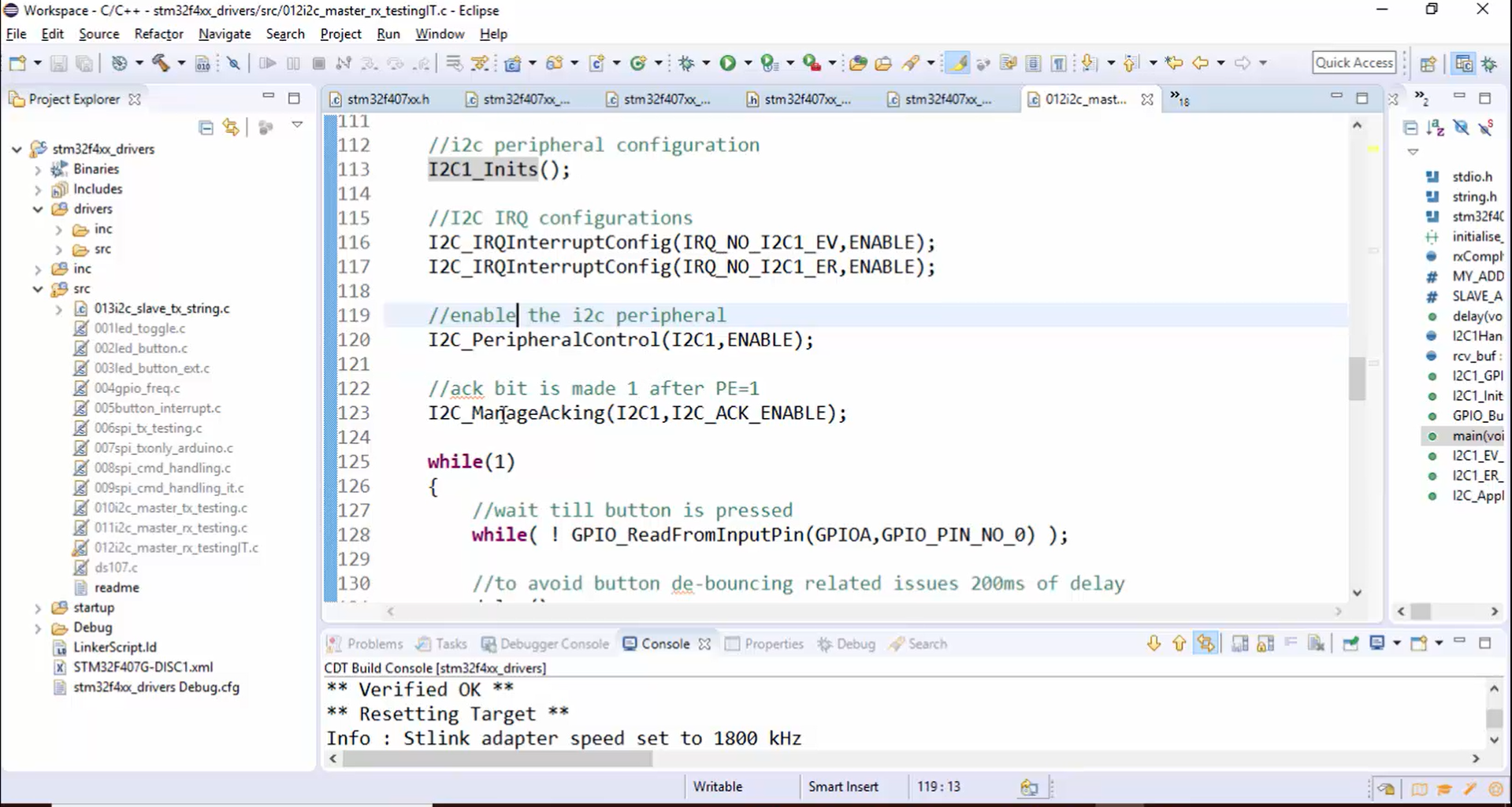
b. GPIO_ButtonInit(), I2C1_GPIOInits(), I2C1_Inits() and I2C IRQ configuration functions shown in Figure 4 are required so keep it as it is.

Peripheral control, manage ACKing functions in Figure 5 are required.
c. Remove the entire while loop shown in Figure 6.

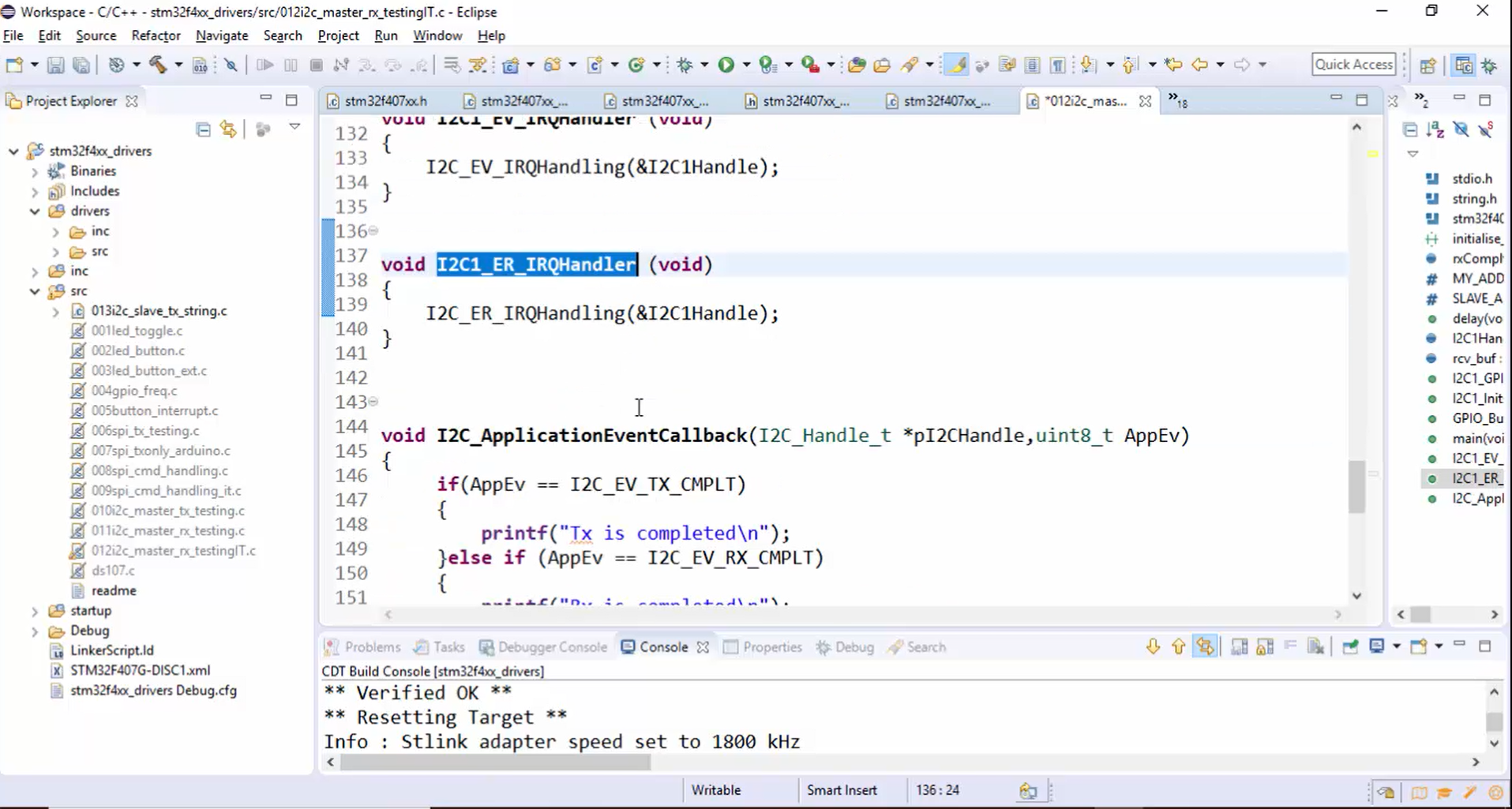
d. Keep the handlers and application callback shown in Figure 7 as it is.
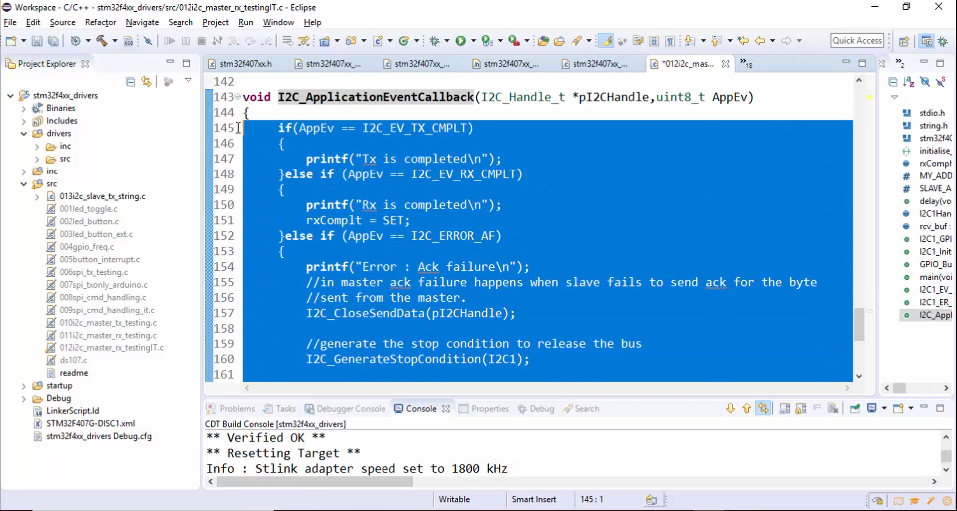
e. Remove the code inside the application callback function (Figure 8).
f. For the I2C1_GPIOInits(), make sure that the pull-up is activated (Figure 9).

g. Remove the code shown in Figure 10.

h. rxComplt flag variable (Figure 11) is not required. Let’s remove that.

i. In this case, the slave address is 0x68. Therefore, remove the MY_ADDR macro shown in Figure 12.

j. Change the name of the buffer to Tx_buf, and let’s have some message in it, as shown in Figure 13. Ensure that the total number of bytes in a message doesn’t cross the 32 bytes, which is the limitation of the Arduino code’s wire library. The way of transmitting or receiving more than 32 bytes will be discussed later in this article. For the time being, just make sure that the length doesn’t cross 32 bytes.

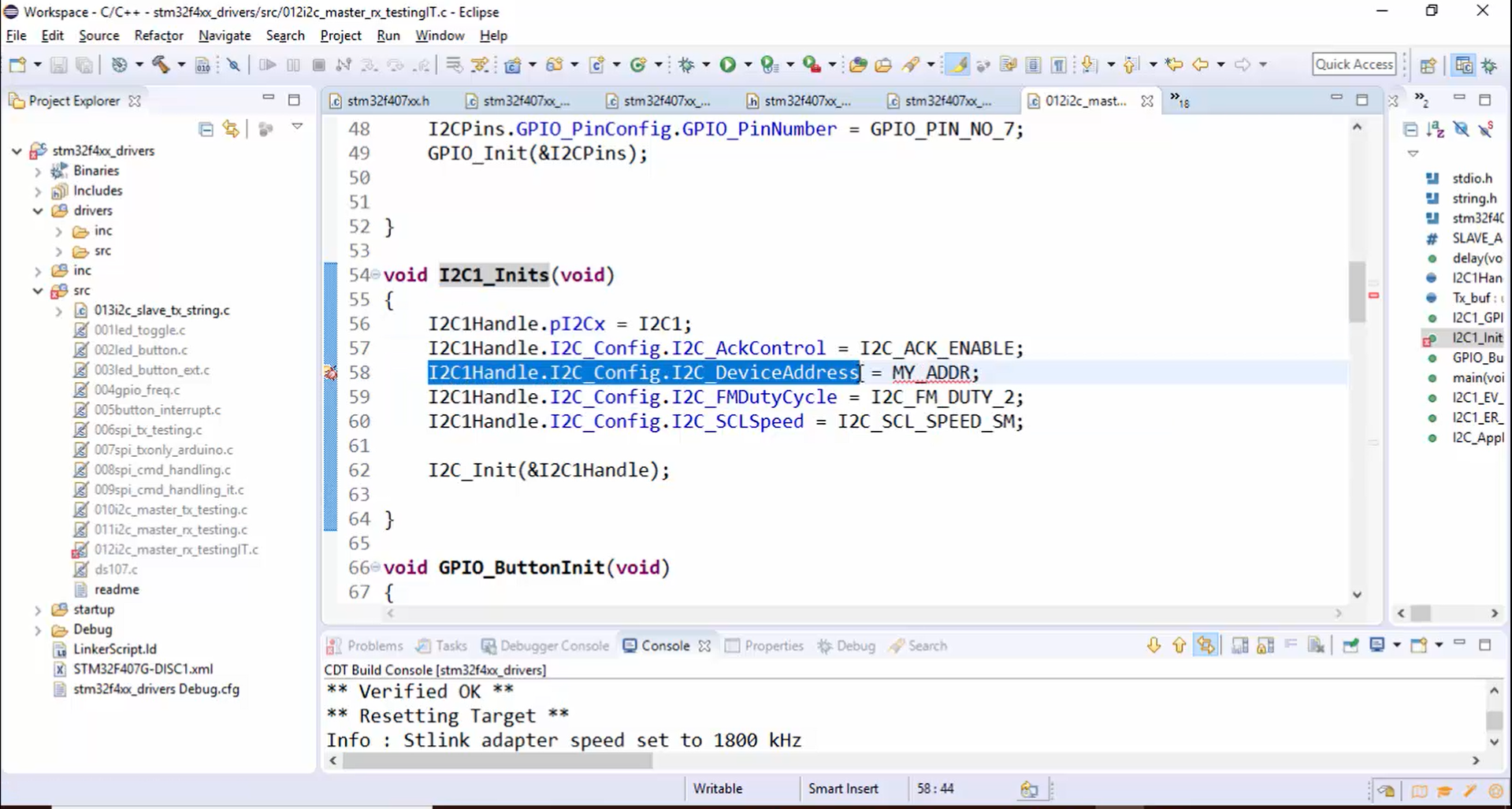
4. Now let’s investigate what we are doing in the I2C1_Inits(). In I2C1_Inits(), I2C_Config.I2C_DeviceAddress field (Figure 14) is very important, and the slave address should be configured here. The slave address is stored in MY_ADDR macro, which is not yet defined. Now let’s define that, as shown in Figure 15. MY_ADDR is nothing but the slave ADDR. Here the slave address is 0x68.

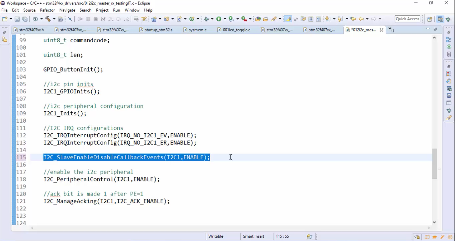
5. You can see that in the main code, the IRQs are enabled (Figure 16). But the interrupt control bits in the I2C CR2 register are not enabled. You have to enable those control bits now because without enabling those interrupt control bits, it is impossible to generate the interrupt for I2C events or I2C errors.

Now let’s create one API for enabling the interrupt control bits in the I2C CR2 register, as shown in Figure 17.
Let’s give the API name as I2C_SlaveEnableDisableCallbackEvents(), and it takes two arguments. One is handle, and another is ENABLE.
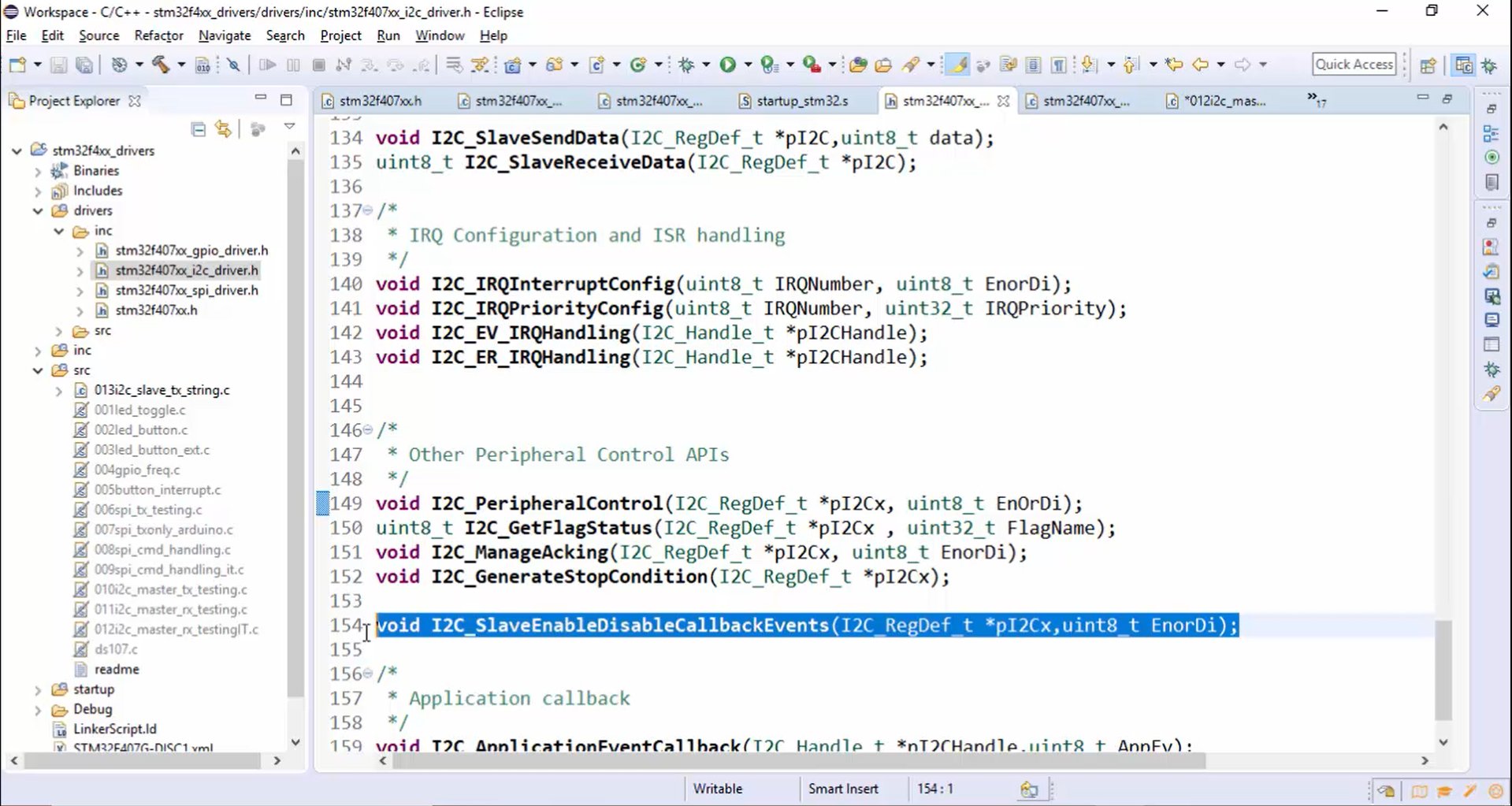
6. Copy the I2C_SlaveEnableDisableCallbackEvents() API, then paste it in the other peripheral control APIs section of the driver.h file and make changes to the arguments, as shown in Figure 18.
7. Now let’s implement the I2C_SlaveEnableDisableCallbackEvents() function in the driver.c file as follows:
If the EnorDi variable is equal to ENABLE, then you must enable the control bits ITEVTEN, ITBUFEN, and ITERREN. Otherwise, you have to disable them (Figure 19).

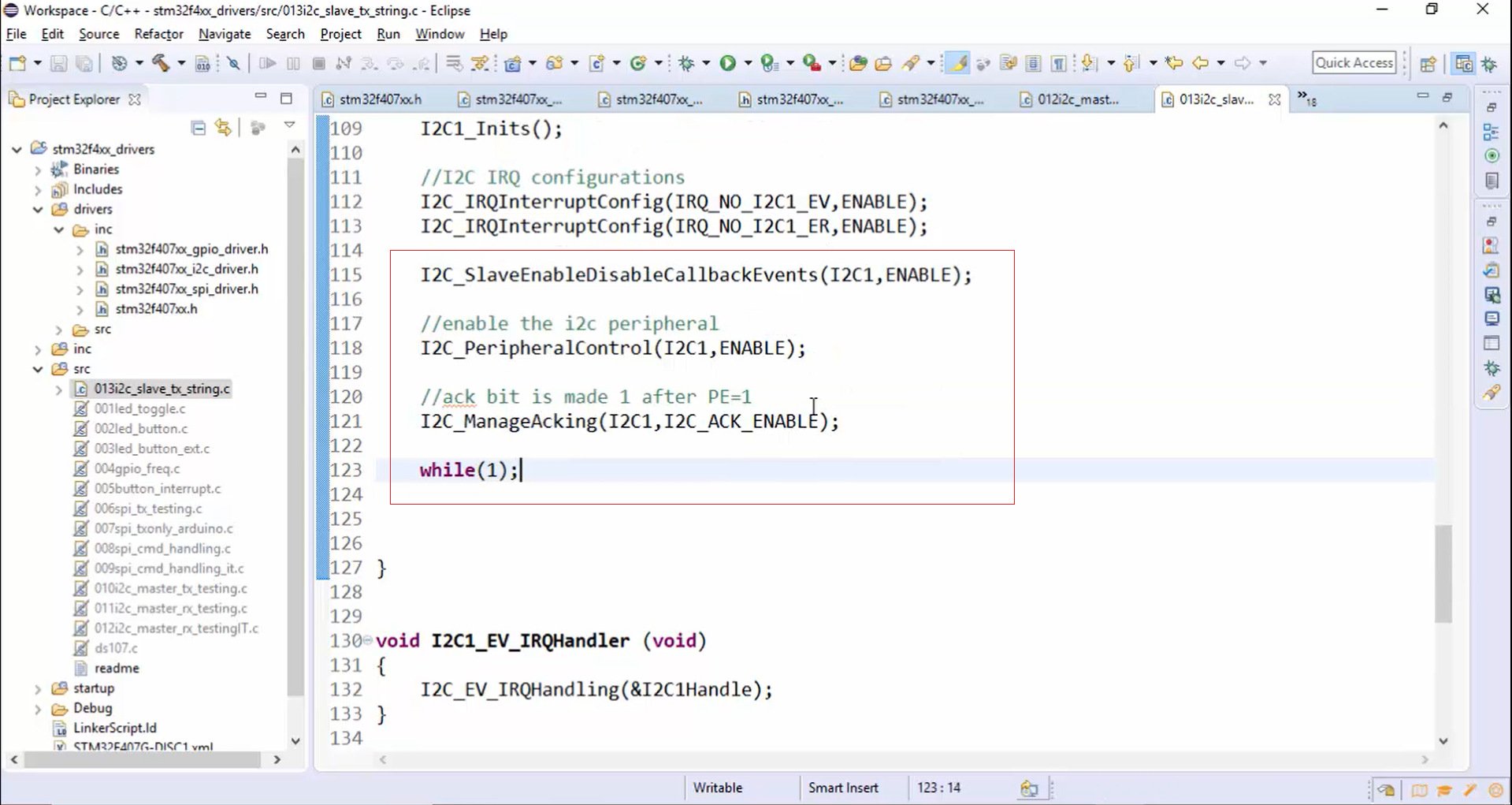
8. Go to the application. I2C_SlaveEnableDisableCallbackEvents() API enables the callback events. After that, the peripheral will be enabled. Then the ACK will be enabled. After enabling a peripheral and ACK, the slave just hangs in the infinite while loop, as shown in Figure 20.
9. Whenever a request is received, or events happen, the application event callback will be called. Now let’s implement the application event callback function (Figure 21).
- If the application event (AppEv) is equal to the I2C event data request (I2C_EV_DATA_REQ), then that means the master wants some data, and the slave has to send it.
- If the application event (AppEv) is equal to I2C event data receive (I2C_EV_DATA_RCV), then that means the data is waiting for the slave to read, and the slave has to read it.
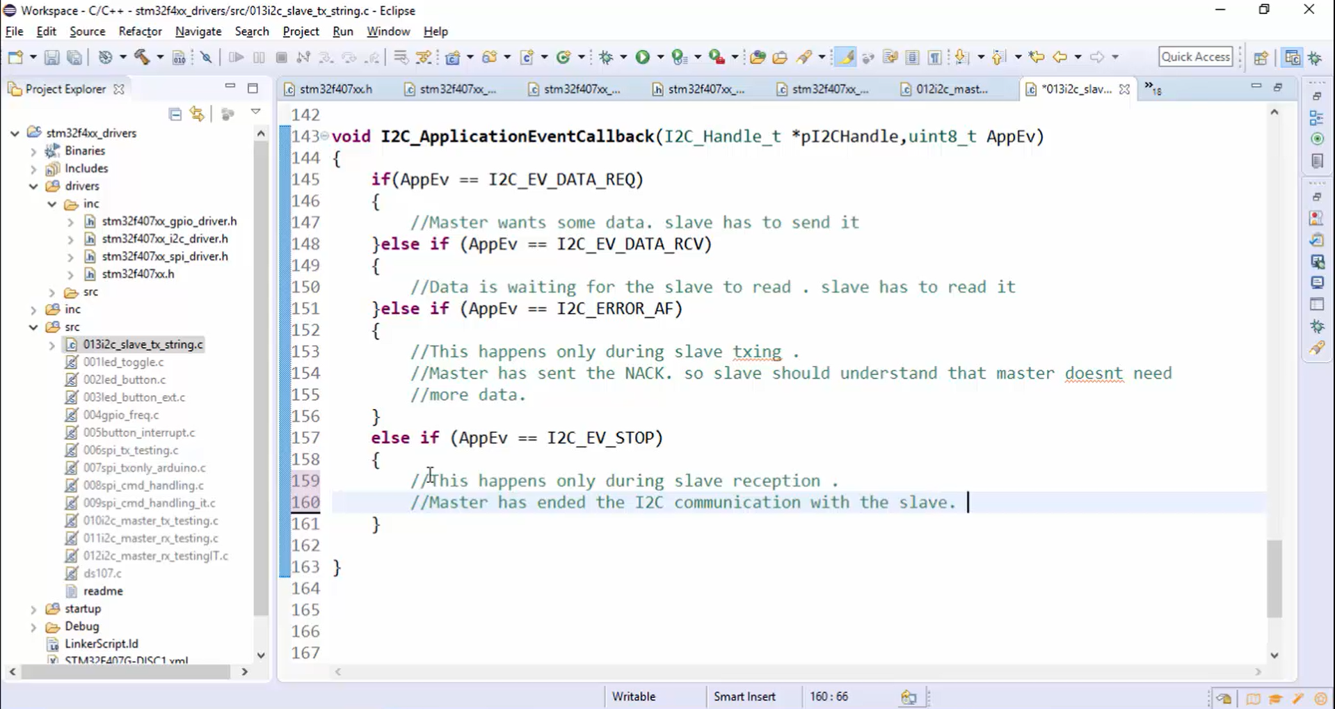
- The application event (AppEv) will be equal to I2C error Ack failure (I2C_ERROR_AF) only during slave transmission. When the AppEv becomes equal to I2C_ERROR_AF, it means that the master has sent the NACK. Therefore, the slave should understand that the master doesn’t need more data.
- The application event (AppEv) will be equal to the I2C event stop (I2C_EV_STOP) only during slave reception. When the AppEv becomes equal to I2C_EV_STOP, it means that the master has ended the I2C communication with the slave. Therefore, the slave should conclude that the master has ended the I2C communication with it.
10. Procedure to read the data from the STM32 slave:
- Master sends command code 0x51 to read the length (1-byte information) of the data from the slave.
- Master sends command code 0x52 to read the complete data from the slave.
Now let’s code according to the above procedure.
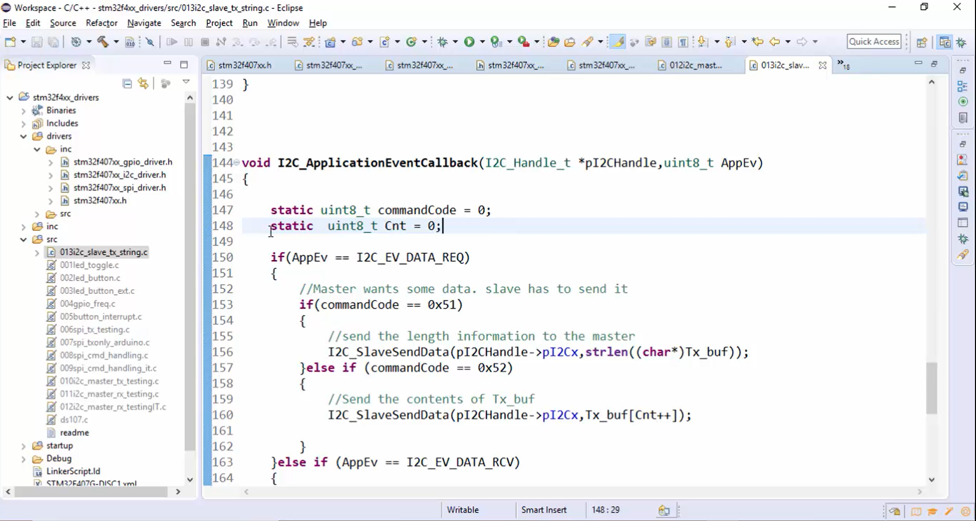
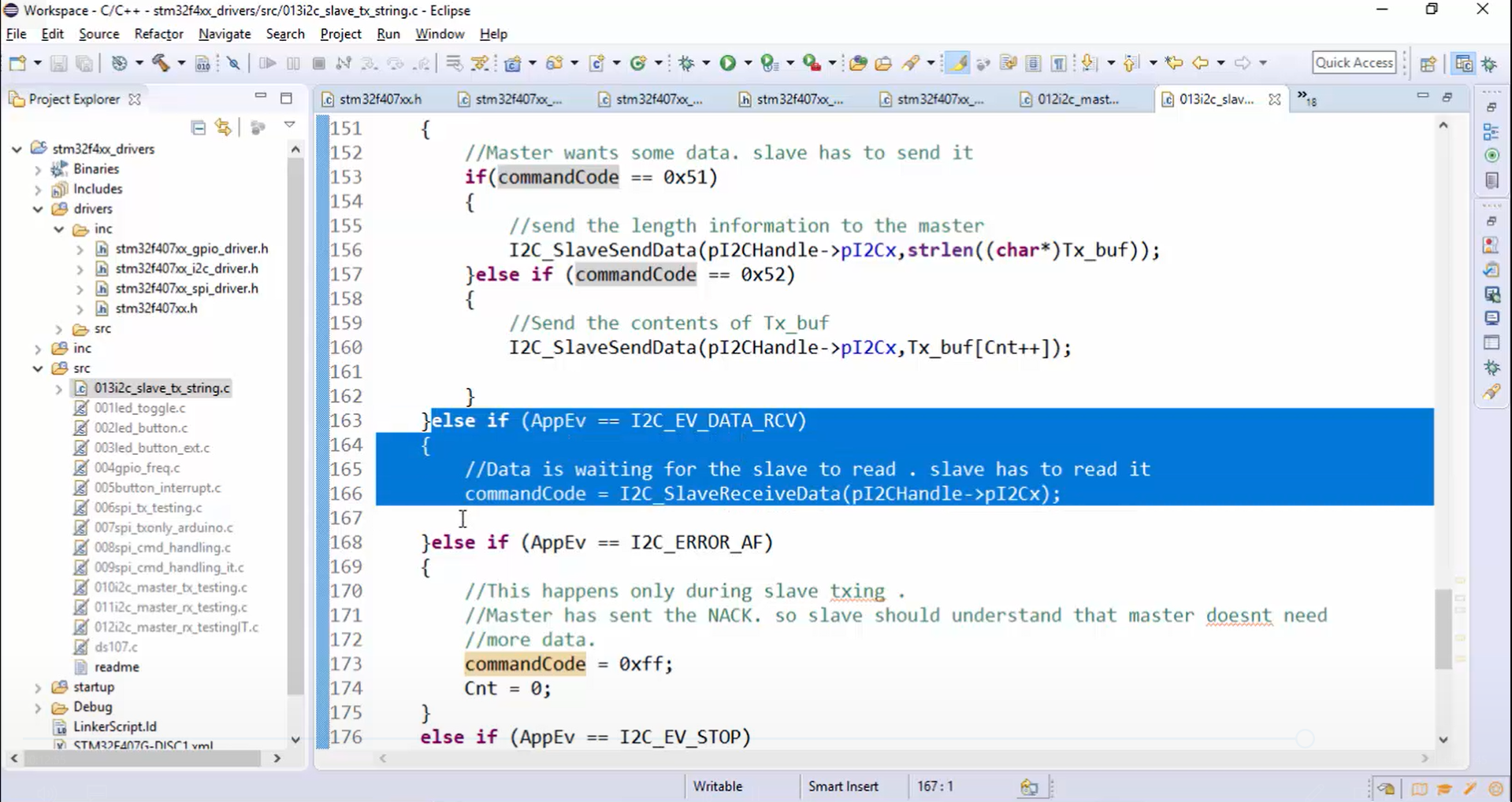
a. First, the master sends a command code to the slave, which is nothing but reading for the slave (or slave data receive). So, whenever data receive happens, the slave stores the command code (Figure 22).
The commandCode variable used to store the command code must be a global variable because the application event callback function exists without hanging anywhere. Therefore, you can’t create that variable locally. Now let’s create a commandCode variable globally, as shown in Figure 22.

b. When the master does read transactions, that is actually a data request for the slave. So, the first if block in Figure 21 will get executed. If the command code received is equal to 0x51, then send the length information to the master. The length information can be sent to the master using I2C_SlaveSendData() API (Figure 23). I2C_SlaveSendData() API takes two parameters, one is handle, and another is data. Here the data is nothing but the length of Tx_buf (strlen(Tx_buf)).
If the command code is equal to 0x52, then send the contents of Tx buf. To send the contents of Tx_buf, again use I2C_SlaveSendData() API. Here instead of length, you have to use Tx_buf[Cnt++] as a second parameter. Now let’s define the Cnt variable. This variable must be global. Otherwise, you can also use a static keyword while defining the Cnt variable, as shown in Figure 23. Static variables are a kind of global variable since the memory for these variables will be allocated in a global space instead of a stack. That’s why even if the application event callback function exits, memory for these variables will not be deallocated, and you can access it from the functions that are called inside the callback function. Even though they are in a global space, you can’t access these variables from other functions because we have used a static keyword. Static means private to that function.
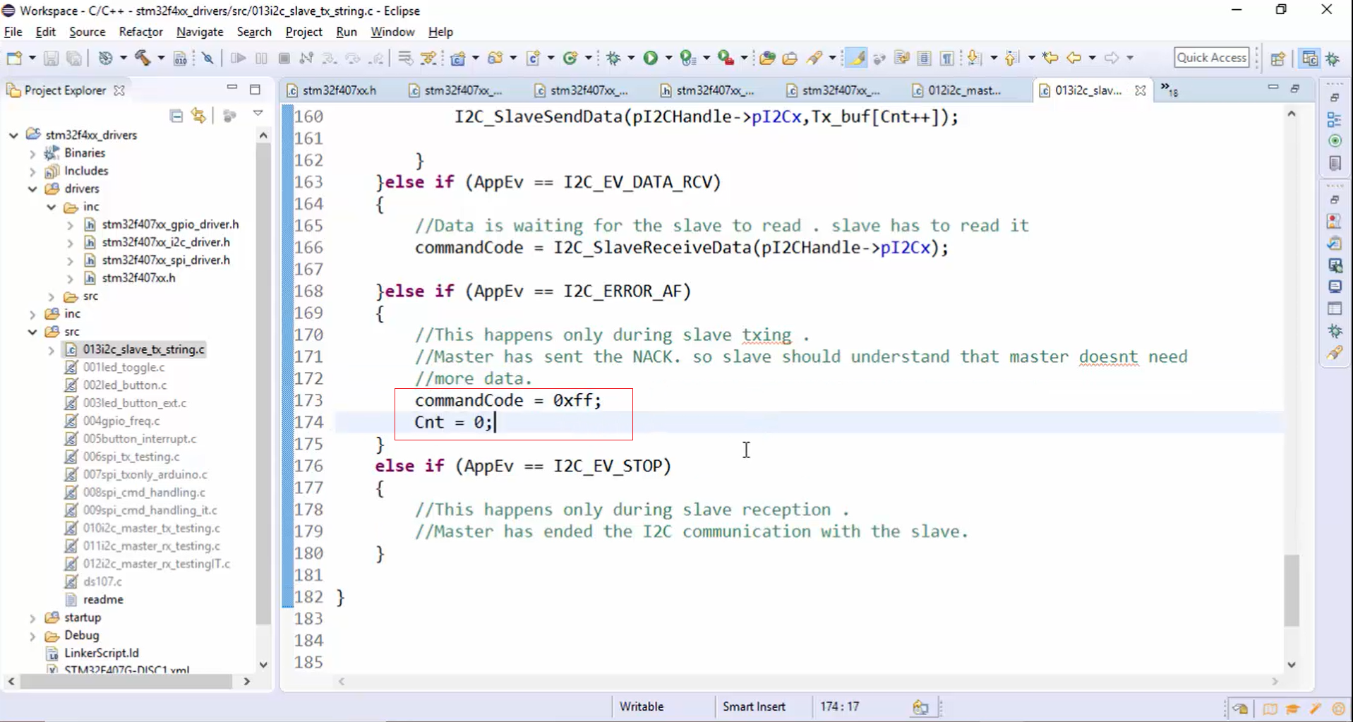
c. Once the command code 0x51 is received, and the slave has sent the length information, the acknowledgement failure happens to indicate the completion of a slave TXing. When an acknowledgement failure occurs, invalidate the commandCode variable and reset the Cnt variable, as shown in Figure 24.
All these are the ways in which the slave responds to the various I2C transactions, and remember that all the steps that are coded above depend upon different types of I2C transactions used in your application. The application callback event function here is coded purely with respect to the data read, and data write transactions.
For example, first, the master generates I2C transactions to read the one-byte length information. So, first, the sending command to slave event will be generated. Therefore, in the slave code, the if condition shown in Figure 25 will be executed, and the slave stores the command code, which is received. This is nothing but a write I2C transaction, which results in a read for the slave.
Master reading response from the slave is nothing but a read transaction. In this read transaction, the master reads the length information from the slave. Read results in data request in the slave. Therefore, the if block shown in Figure 26 will be executed, and master will read the length since it has already sent the command code as 0x51.

After that master generates two more I2C transactions to read length bytes of data from the slave. For that, first, perform a write transaction. The master sends command code 0x52. Again, the if block in Figure 25 will get executed, and now the command code will be 0x52. Then a read transaction is initiated by the master, and the block shown in Figure 27 will be executed, which is nothing but sending the contents of Tx_buf. Whenever TXE is set, the if block in Figure 27 will get executed, and the slave sends the data byte by byte to the master. When the transmission ends, the ACK failure will be generated, and the block in Figure 28 will get executed.