Exploring UART functional block
Now let’s explore the USART functional diagram in the STM32f4xx microcontroller. For that, let me take you to the USART section of the reference manual.
Figure 1 shows the block diagram of the USART hardware.
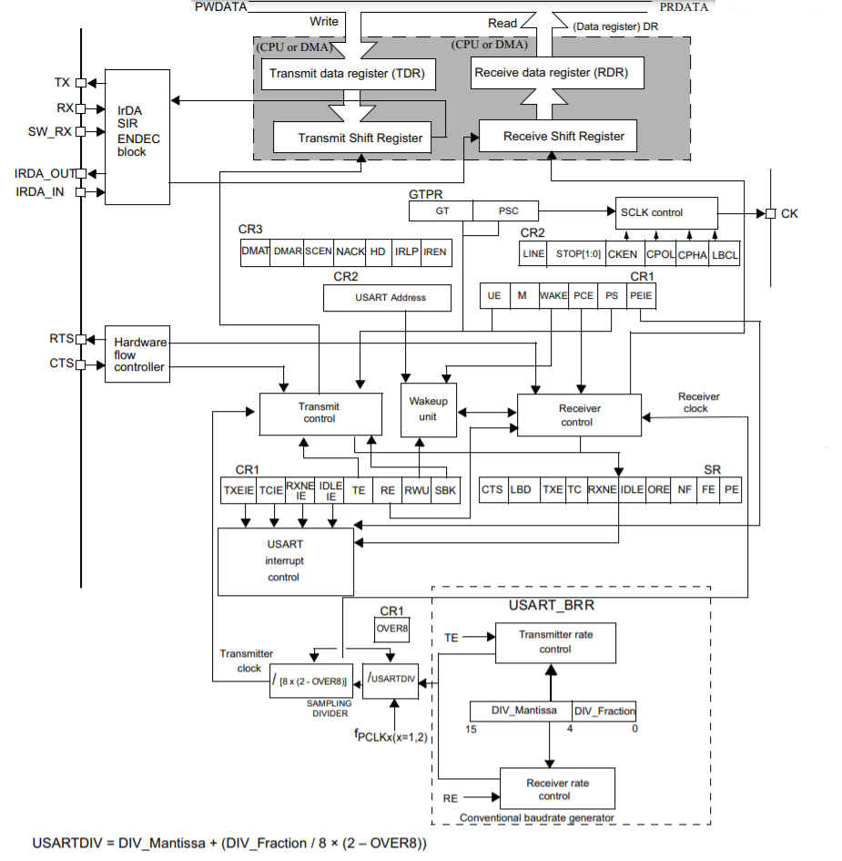
This hardware block can be used for both synchronous and asynchronous data transfer. But we are currently interested in UART that is asynchronous.
In Figure 2, you can see four important pins that are used in UART communication. They are TX, RX, RTS, and CTS. The TX and RX pins are used to transmit and receive data, and RTS and CTS pins are used for hardware flow control.
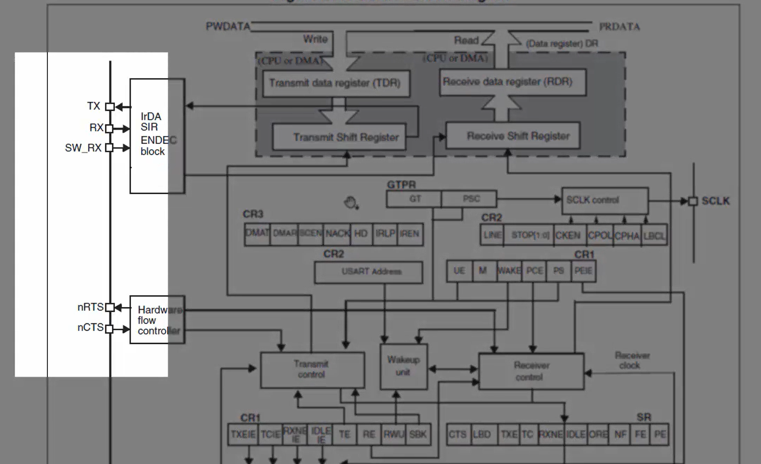
If this hardware block is used in synchronous mode, then the serial clock will be used since the UART is a full-duplex in communication. Full-duplex means you can transmit and receive data simultaneously.
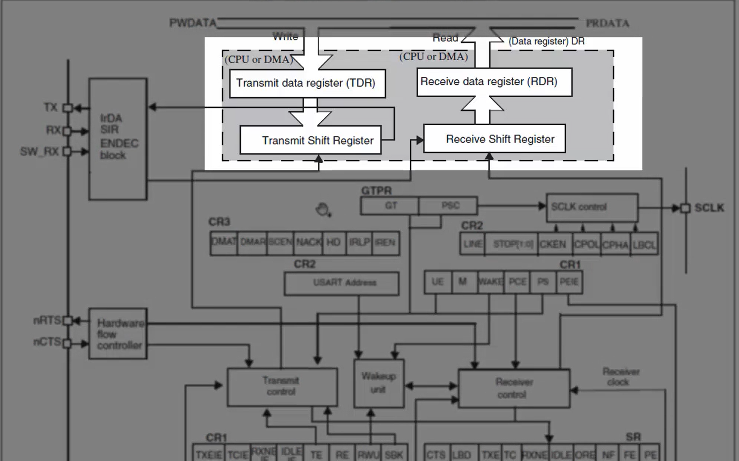
There are two data registers (Figure 3) to achieve full-duplex communication. One is transmit data register, and another one is receive data register. Each data register has its associated shift register.
There are a couple of control registers (Figure 4) having various control bits used to control the transmission block as well as the receiver block.
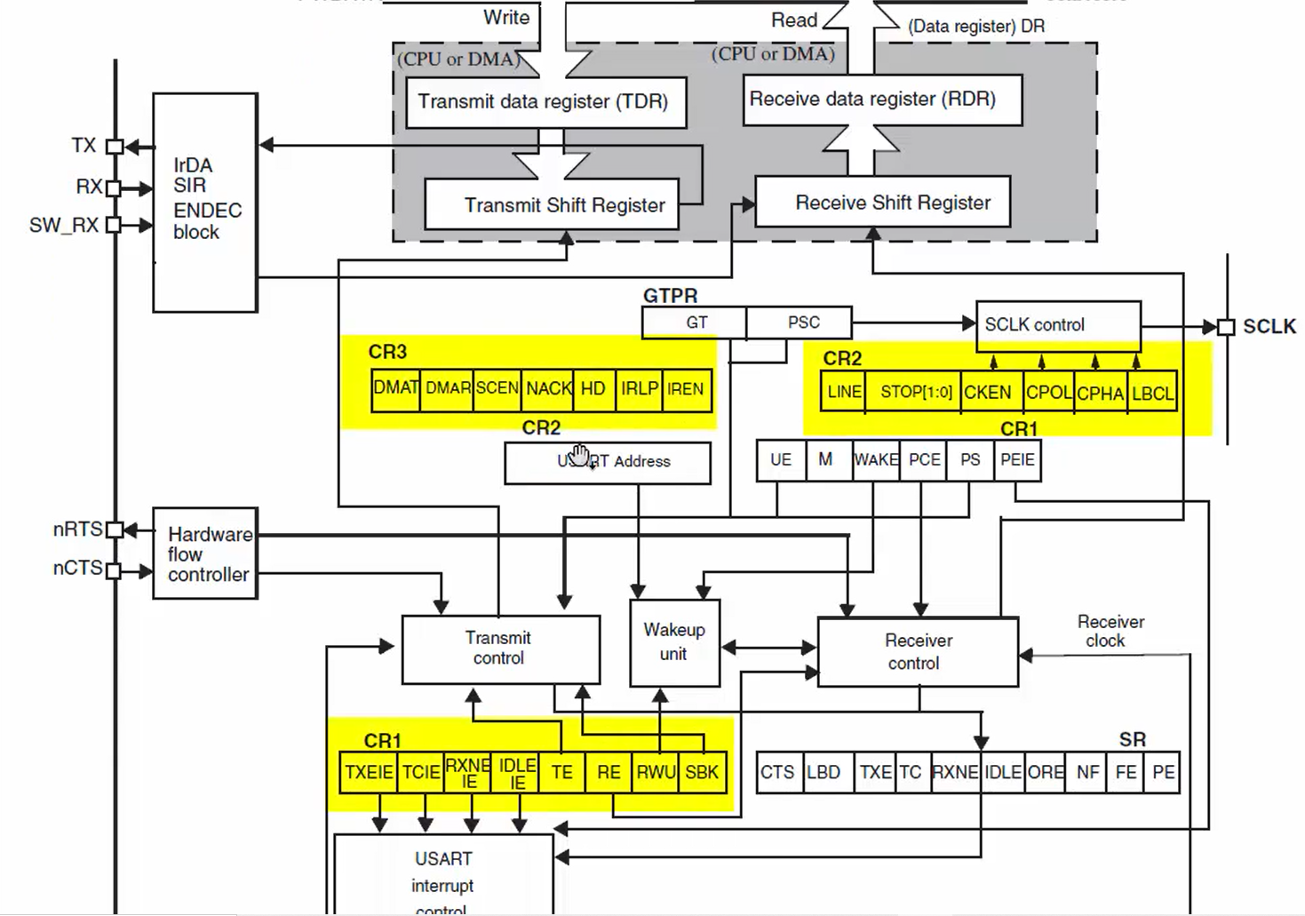
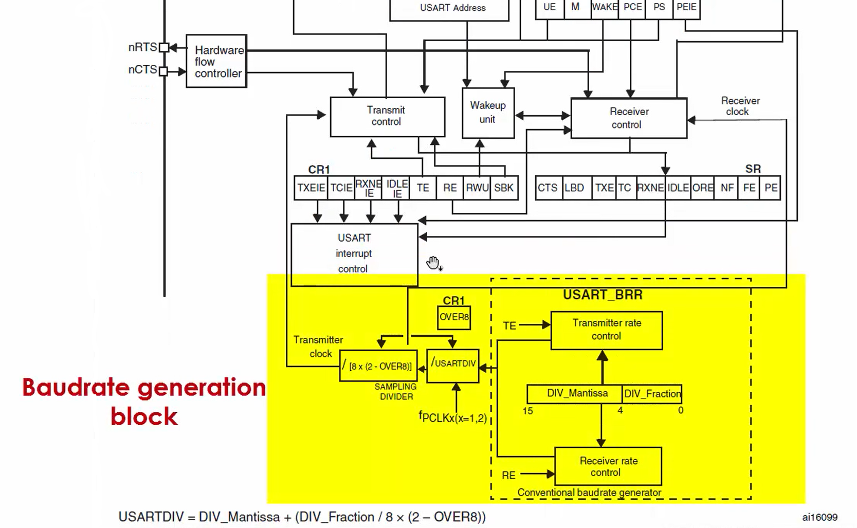
Figure 5 shows the baud rate generation block, which is used to generate the proper baud rate for the data transfer. You can see that the peripheral clock undergoes various divisions to produce the proper baud rate for the data transmission.
The USART_BRR register must be configured properly with mantissa and fraction fields to produce the desired baud rate.
In the next article, let’s see UART peripheral clock.
FastBit Embedded Brain Academy Courses
Click here: https://fastbitlab.com/course1

