UART Parity
Adding a parity bit is the simplest method of error detection.
Parity is simply the number of ones appearing in the binary form of a number.
For example, the number 55 has a binary form 0b00110111, and the parity is 5, which is an odd number. To get the parity value, just count the number of one’s appearing in the binary pattern.
There are two options in parity selection.
- Even parity
- Odd parity
Now let’s discuss them one by one.
1. Even parity:
In the previous example, we saw that the number 55 has an odd number of one’s. In the case of even parity, the parity bit is set to one to make an entire number of one’s including parity bit as even. So, if the number of one’s in a given set of bits excluding the parity bit is odd, then the parity bit will be set to 1 in order to make the number of one’s in the entire set of bits, including the parity bit as even. If the number of one’s in the given set of bits is already even, as in the case of number 54 (00110110), then the parity bit is set to zero in order to make the entire set of bits even. This is how even parity works.
2. Odd parity:
When using odd parity, the parity bit is set to 1 if the number of one’s in a given set of bits excluding the parity bit is even, making the number of one’s in the entire set of bits including the parity bit as odd. If the number of one’s is odd in the given data bits, then the parity bit is set to zero.
If you are still confused, simply remember that the even parity results in an even number of 1s, whereas odd parity results in an odd number of 1s, when counted including the parity bit.
Why use the parity bit?
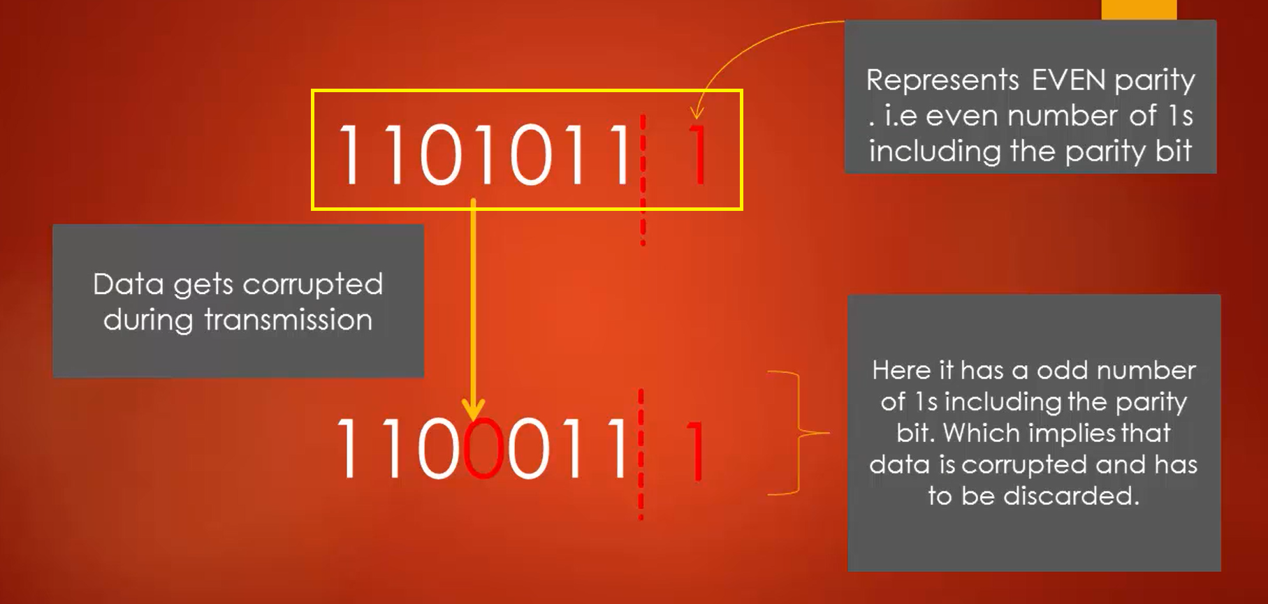
The parity bit is used to detect errors. Let’s say we are transmitting the data 1101011, i.e., decimal 167, assuming an even parity bit is added to it. The data being sent becomes 167, marked in Figure 1, and there the red one indicates the parity bit.
Let’s assume in the course of transmission, the data gets corrupted, and one of the bits got changed. Ultimately the receiver receives the second data pattern in Figure 1, in which the 4th bit is corrupted. We know that the data is sent according to the even parity.
Now count the number of one’s in the received data, including the parity bit. You will get 5. But that sounds wrong because there should be an even number of one’s including the parity bit, in the case of even parity selection since both devices agree upon the parity logic. This makes the receiver realize that the data is corrupted, and it will eventually discard the data and then wait or request for a new frame to be sent.
In the following article, let’s explore UART functional block.
FastBit Embedded Brain Academy Courses
Click here: https://fastbitlab.com/course1