STM32F4 Discovery and Nucleo: Board Details
If you have an STM32F407VG discovery board, then it actually comes with two flavors. One is an older board, and another one is a newer one. So, first, you have to check the name of your board.
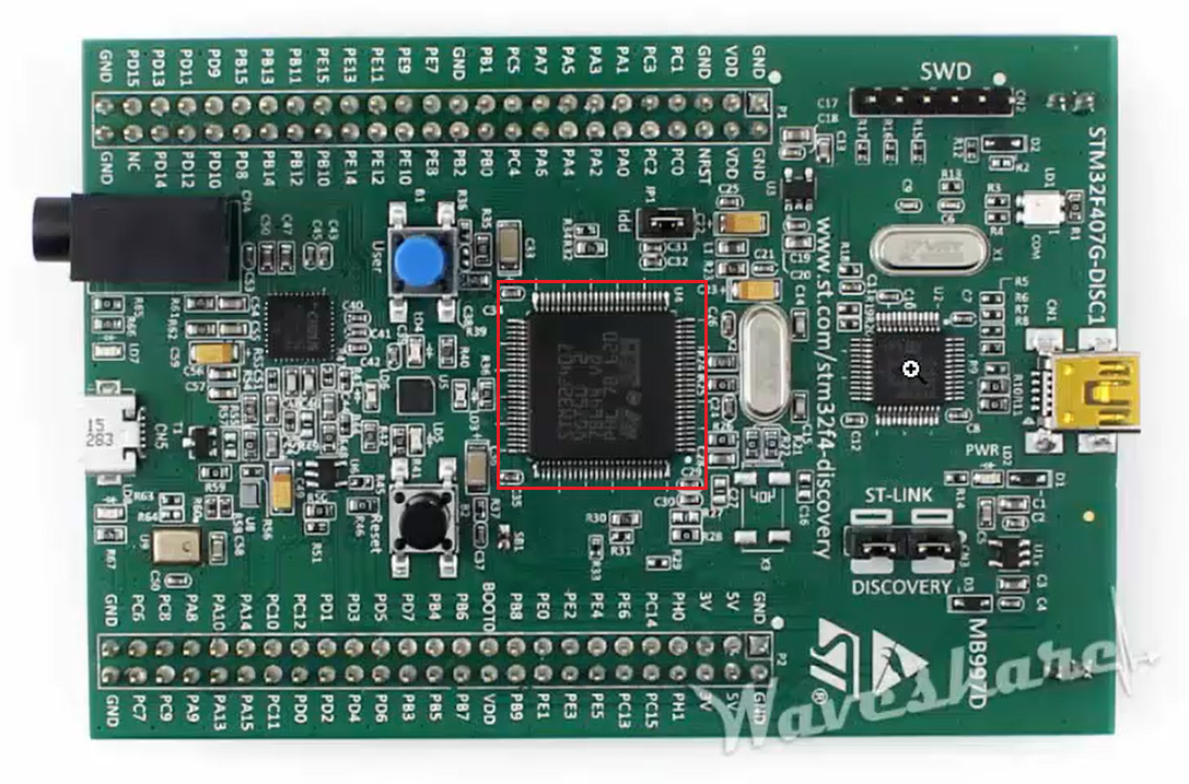
For example, in Figure 1, you can see the image of the board. There you can see that the name is STM32F407VG – DISC1.
DISC1 means it’s a newer board. If you don’t see this name, then it’s an older board.
Remember that MB997D is a board identification number for the newer STM32F407VG discovery board and MB997C is for older boards. You have to know this difference.
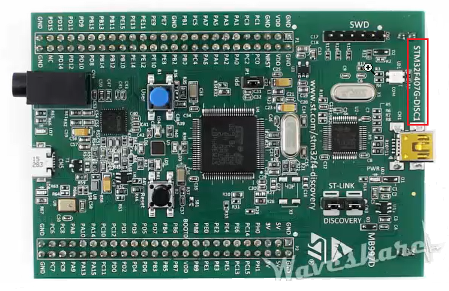
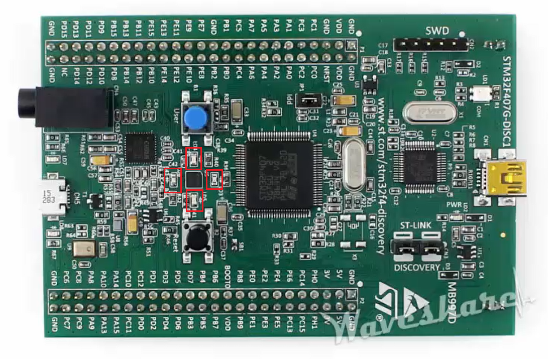
In the middle of your board, you will see one microcontroller (Figure 2). That is the main microcontroller of the board.
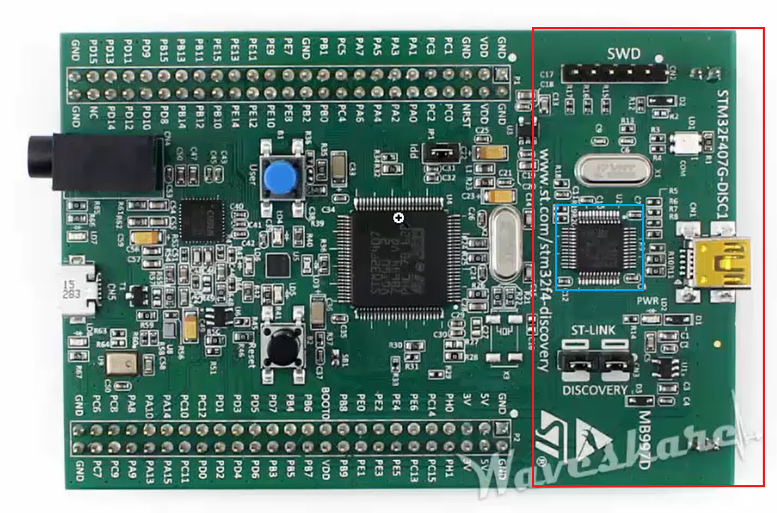
On the right-hand side of your board, you will see one microcontroller (Figure 3), which is the microcontroller used for this ST-Link circuitry. The portion marked in Figure 3 is called as ST-Link circuitry, which is actually in-circuit debugger and programming circuitry.
With this circuitry, you flash the code onto the microcontroller as well as debug the code running on this microcontroller from the host software like Keil or Eclipse.
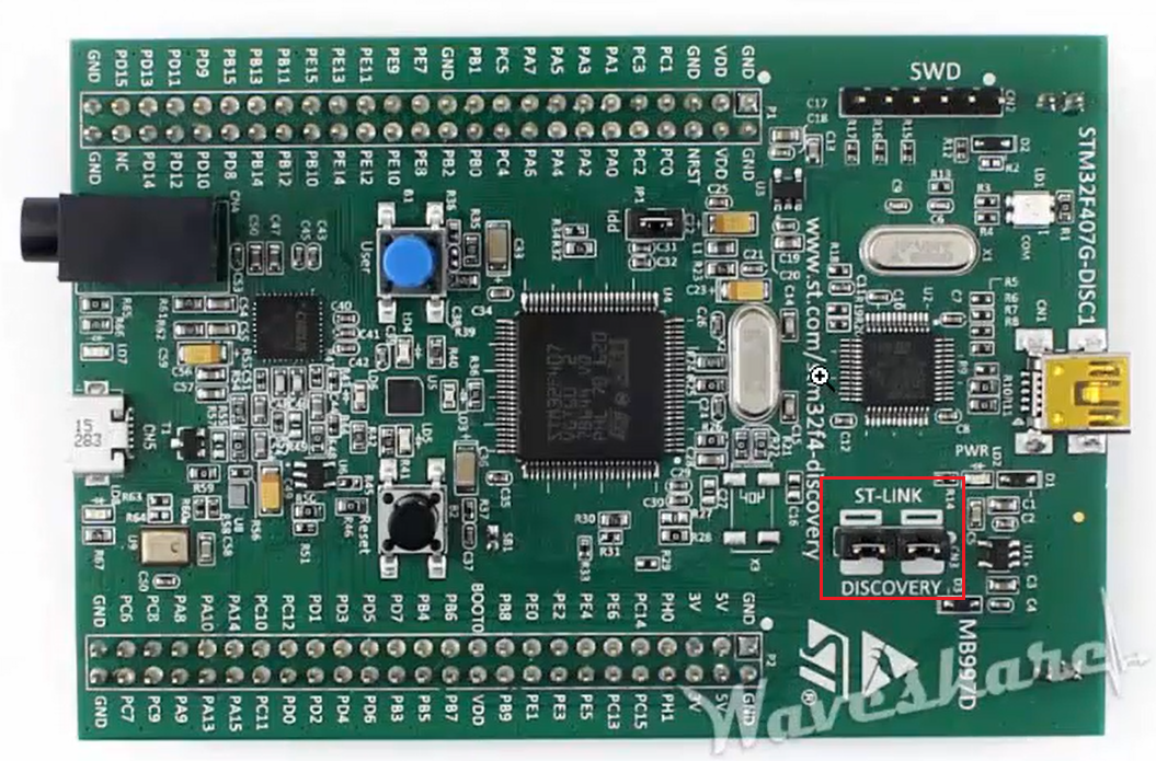
Make sure that the jumpers shown in Figure 4 are connected properly. Otherwise, your PC won’t detect the ST-Link circuitry.
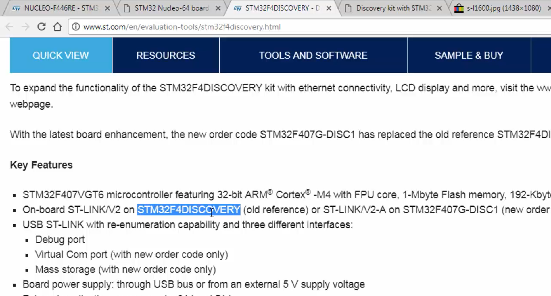
The ST-Link circuitry comes with the firmware in order to operate properly, and in the product description page (Figure 5), they say that the onboard ST-Link used on the old discovery board is ST-LINK/V2, and ST-LINK/V2-A is used in newer boards. That means there are two versions of this ST-Link. The version number V2-A is used in newer boards, and version number V2 is used in older boards.
Now let’s explore this board a little bit.
First, let’s explore the discovery board. For the full features of the board, you have to refer to the user manual. Remember that the chip shown in Figure 2 is the main microcontroller, and the part number or name of the microcontroller is written on this microcontroller itself. You can have a close look at the microcontroller.
The board shown in Figure 2 is a discovery board, which has four LEDs.
In Figure 6, you can see the LEDs. It has four LEDs. The blue button on the board is the user button, and the black button is a reset button.
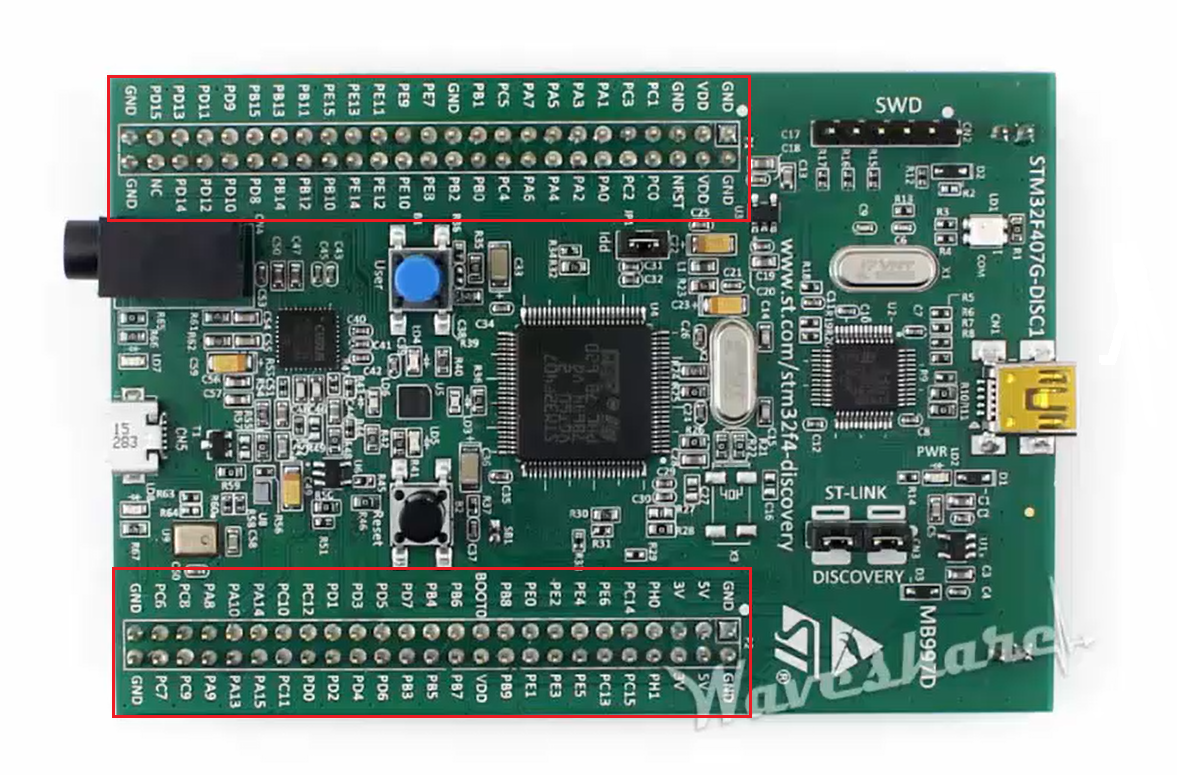
It also has various pins on the expansion header, as shown in Figure 7, in order to connect various other peripherals such as LED and other sensors.
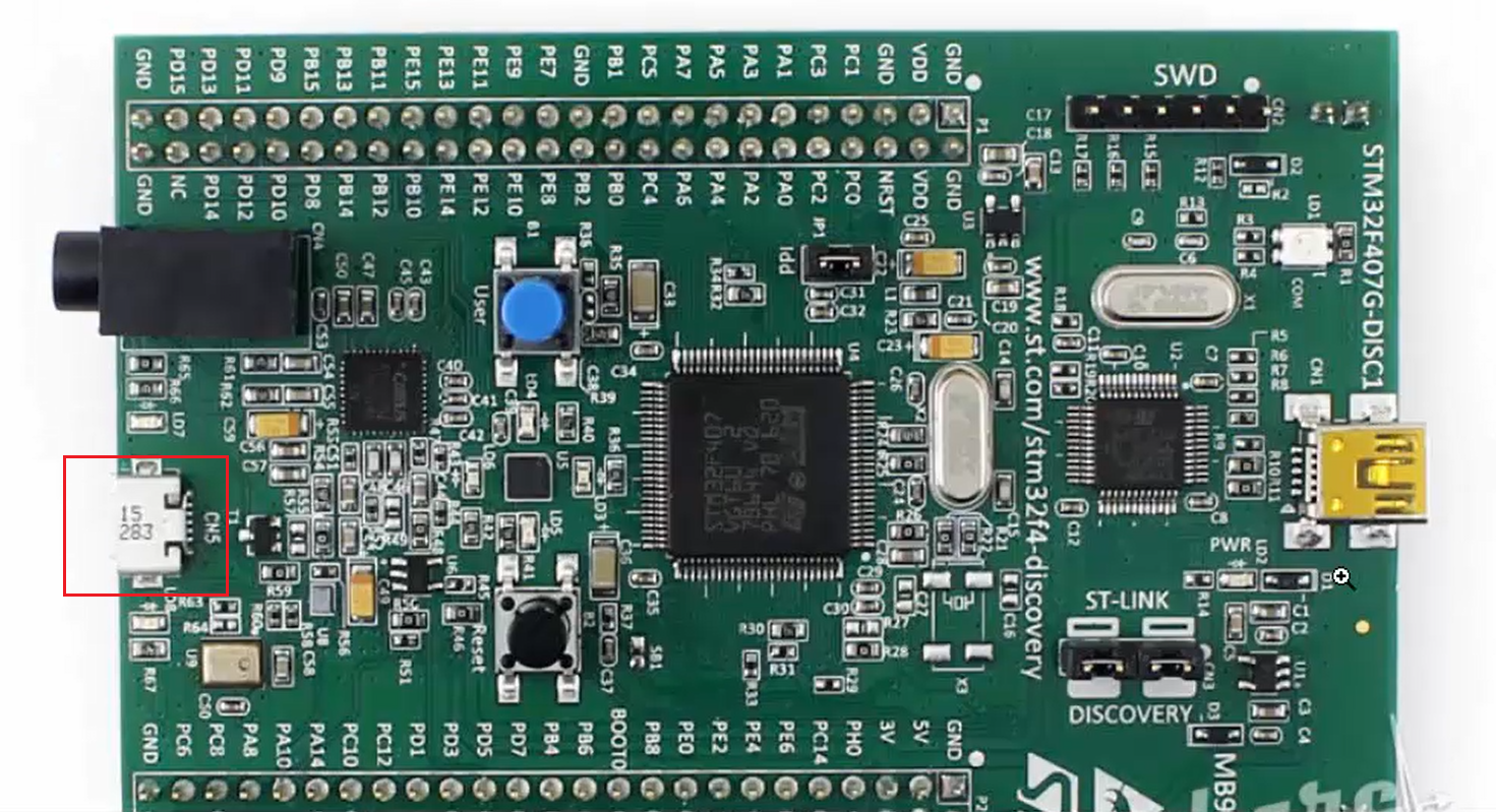
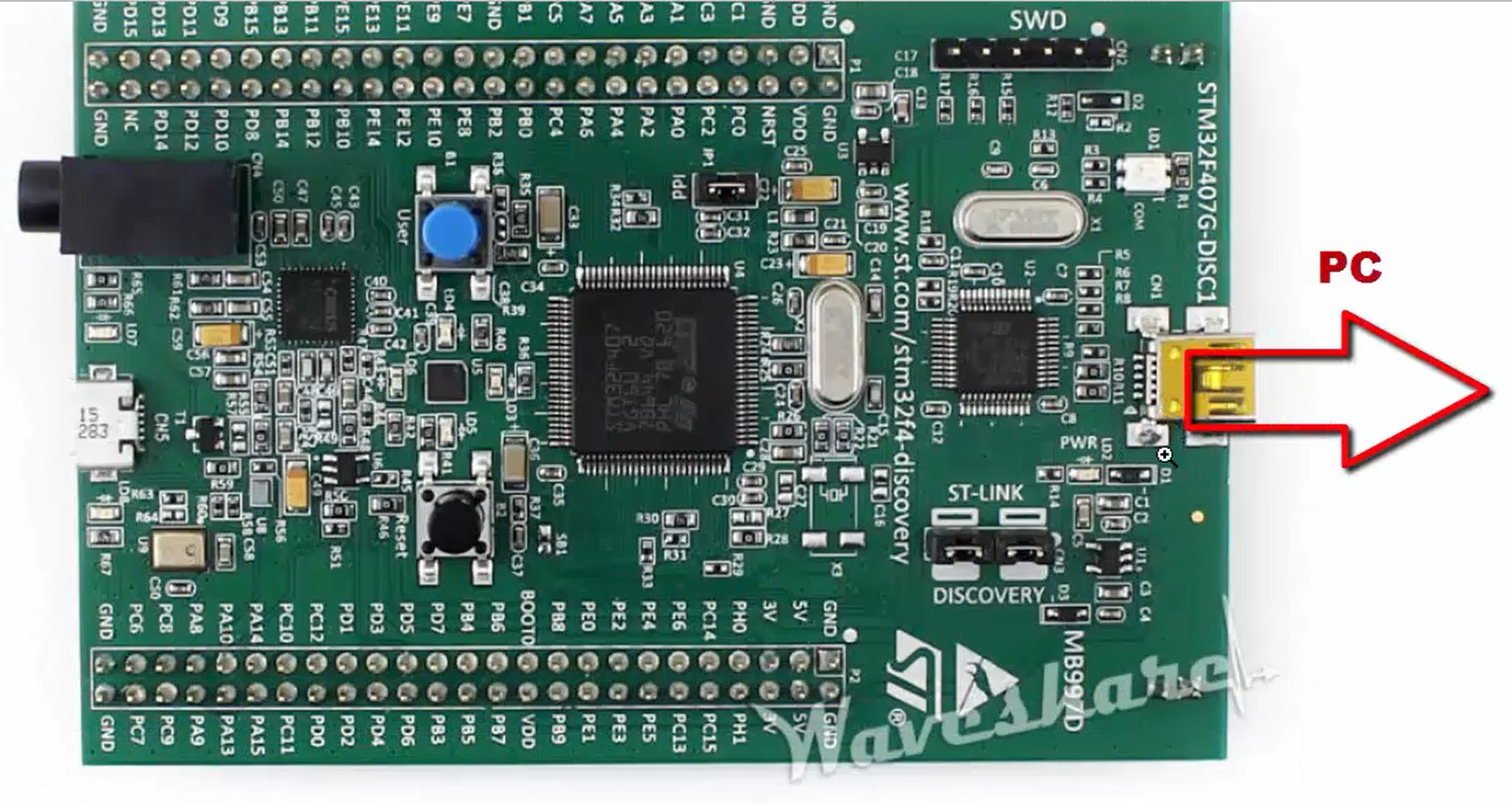
It also comes with one micro-USB connector (Figure 8), which is used for some USB-related experiments. Board is connected to the PC through the mini-USB cable. Therefore, you have to take one mini-USB cable and then connect that into the mini-USB connector on board (Figure 9).
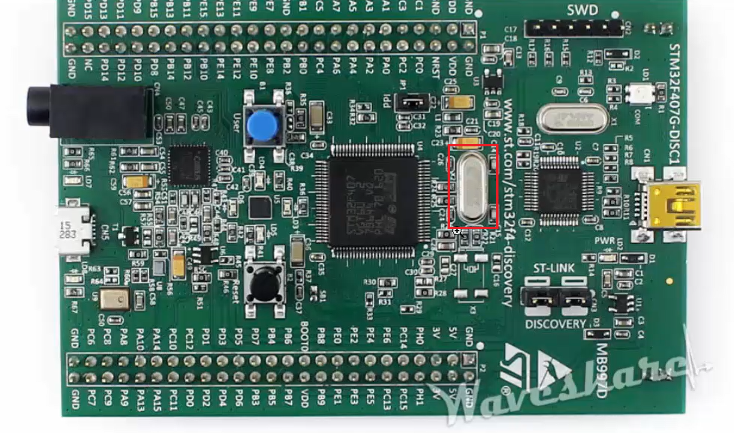
Please note that this board comes with an 8MHz of external clock (Figure 10), which is very close to the main microcontroller.
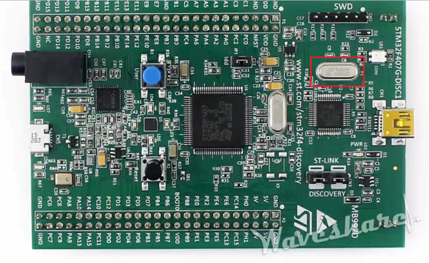
Another clock shown in Figure 11 is for the ST-Link circuitry. But by default, the microcontroller doesn’t use an external clock. It is there on the board, but it is not used until you write some code in order to switch the clock to the external clock.
The microcontroller will always come with one internal clock that we call an internal RC oscillator. By default, the microcontroller uses its internal RC oscillator.
The STM32 discovery board is rich in features compared to the Nucleo board. It contains lots of mem sensors, and you can get the details about the sensors on the user manual.
Nucleo board
The Nucleo board has fewer features, and the important thing about this hardware is, it is Arduino compatible. It supports Arduino and ST morpho connectivity. It is possible to use some of the Arduino shields onto this hardware. You don’t find any sensors on board. It doesn’t come with any sensors.
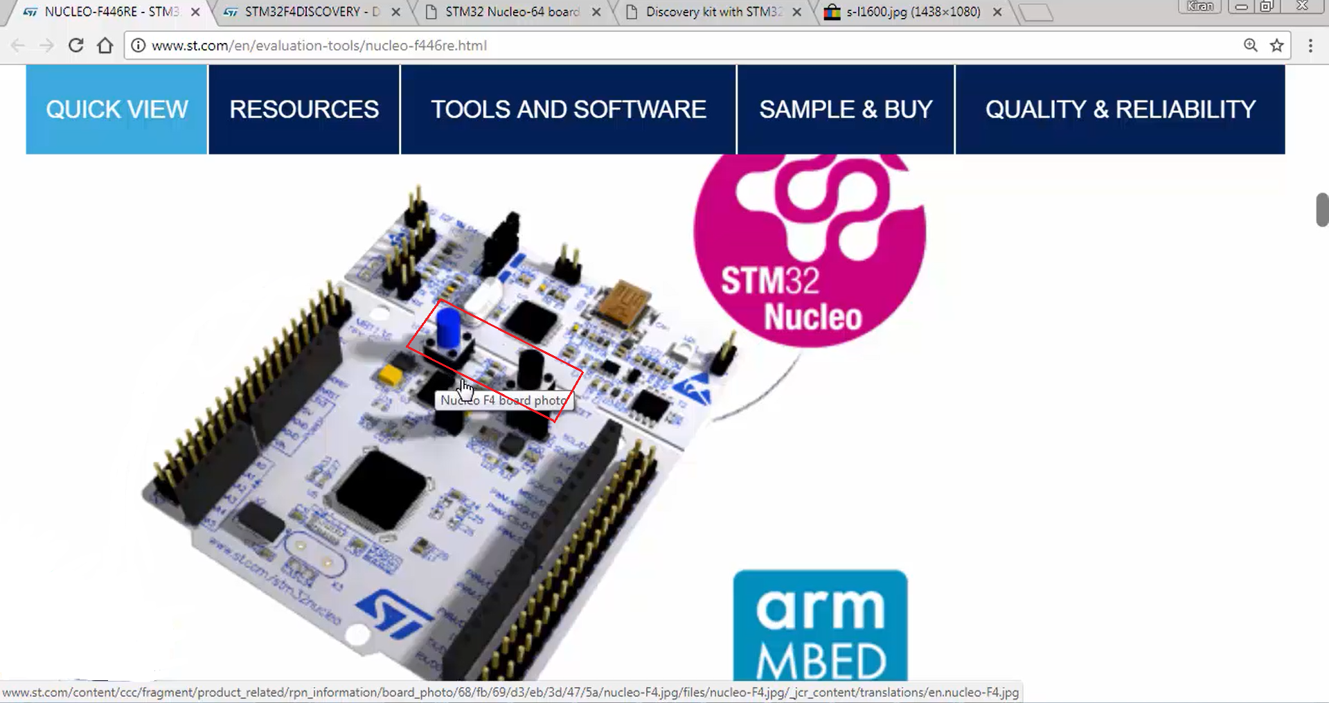
On Nucleo, you don’t find many LEDs. Only one LED is present. Similar to the discovery board, it also has a user button (blue colored) and a reset button (black colored), as shown in Figure 12.
The Nucleo board doesn’t come with the onboard external oscillator. One major advantage in the case of the Nucleo board is, it has virtual COM support. That means when you connect your Nucleo board to the PC, it will enumerate as the virtual port.
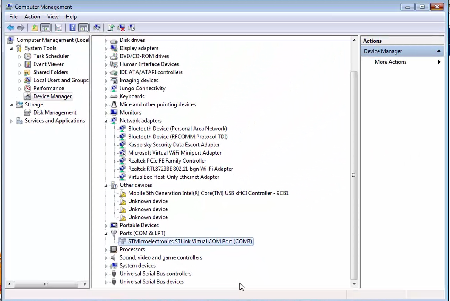
Suppose if you open your device manager, you can see that the Nucleo board is actually enumerated as a COM3 port (Figure 13). That means it is possible to talk to the board over the UART by just connecting the Nucleo board to the PC, but that feature is not available in the discovery board.
For this, you have to make some settings, which are mentioned in the user manual of the discovery board.
Go to the user manual of the discovery board and go to the section ST-LINK/V2-A VCP (Virtual Com Port) configuration.
The ST-LINK/V2-A, i.e., a newer board, supports a virtual COM port on U2 pin 12 (ST-LINK_TX) and U2 pin 13 (ST-LINK_RX). But these pins are not connected to the USART of the STM32F407 microcontroller for mbed support. This is the problem in order to enumerate the virtual COM port support. That’s why they give two solutions as follows:
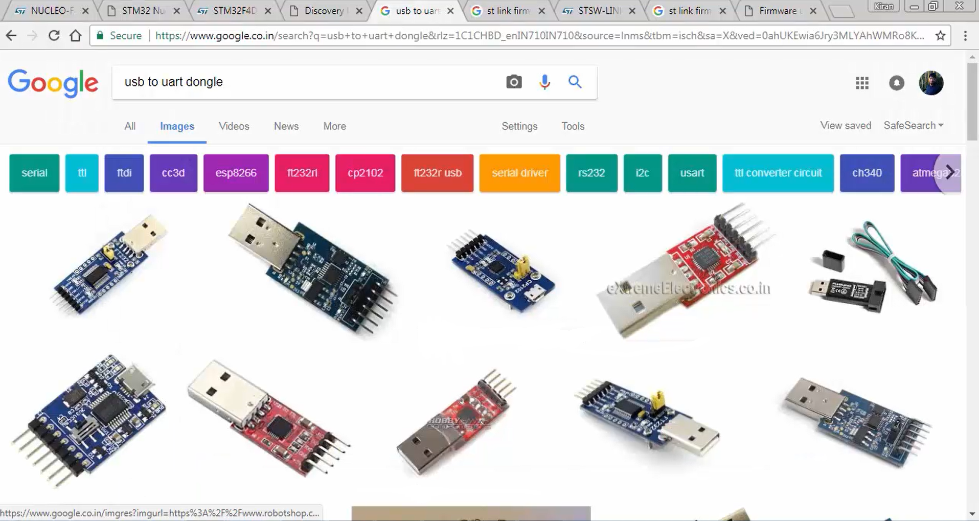
1. One is you use UART to USB dongle from the market. Those are actually very low-cost devices. You have to buy one dongle, i.e., USART to the USB dongle.
Figure 14 shows some of the very low-cost dongles you can use to get the virtual COM port support.
2. You have to short the wires marked in Figure 15, which is actually a TDS process, and I suggest you not do that because you may end up damaging the board.
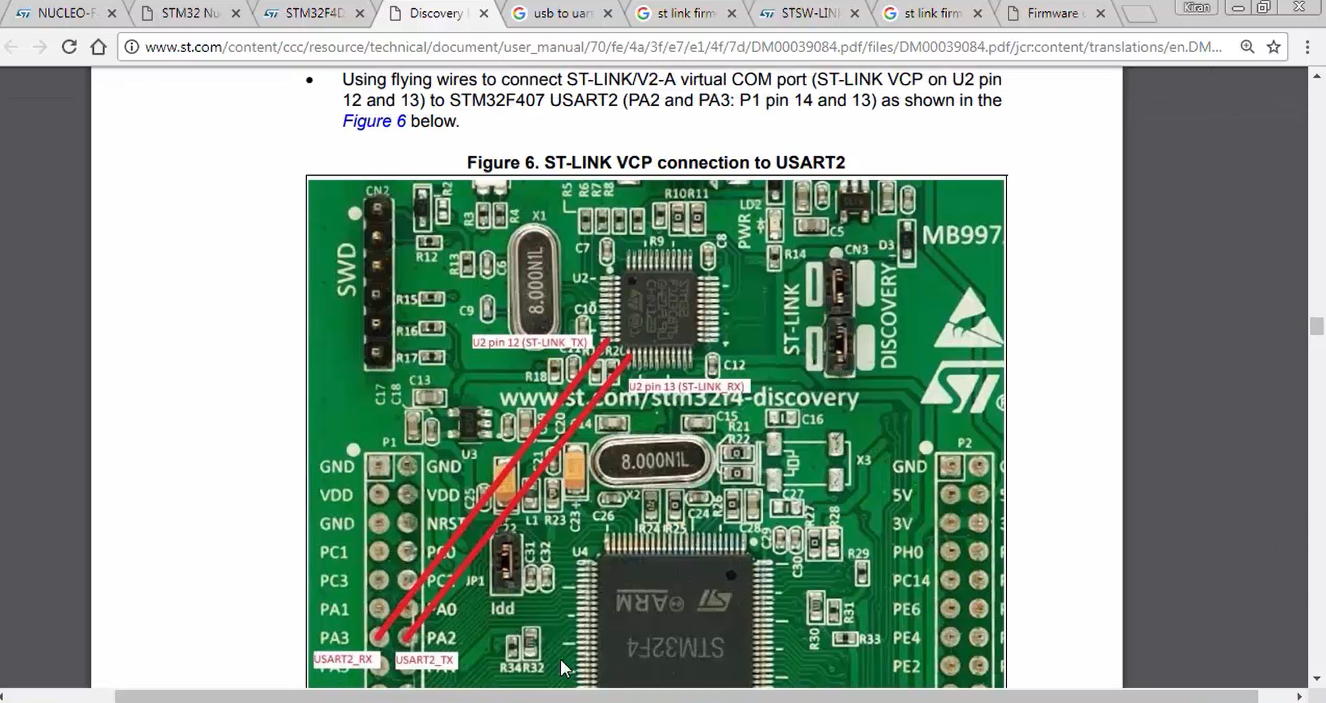
That means the virtual COM port support is not directly available on the discovery board. Whereas on the Nucleo, it is already available since the connection shown in Figure 15 already exists on it. So, you can communicate with the Nucleo board from your PC over UART without using any external USB to UART converted dongle.
In the following article, let’s learn ST-Link Driver Installation.
FastBit Embedded Brain Academy Courses
click here: https://fastbitlab.com/course1