Exercise-003 Hardware connections
In this article, let’s talk about the Hardware connections.
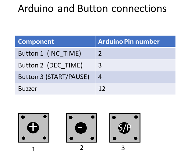
Look at Figure 1, Arduino and Button connections table.
There are three buttons: Button 1, Button 2, Button 3.
And the first button is Increment time, the second button is Decrement time, and the third button is the START/PAUSE button, and these are connected to 2, 3, 4 PINs of the Arduino board. And there is also one Buzzer.
You can either use an active buzzer or a passive buzzer; the Buzzer is connected to PIN 12.
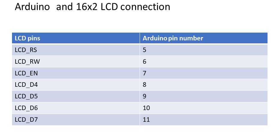
And also, the project uses 16×2 LCD, and Figure 2 shows the connection between LCD pins and the Arduino pin.
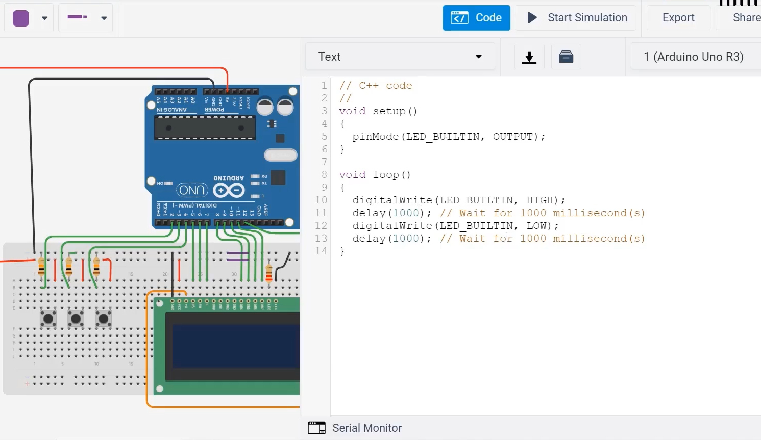
Let’s make the connections. Go to the Tinkercad.
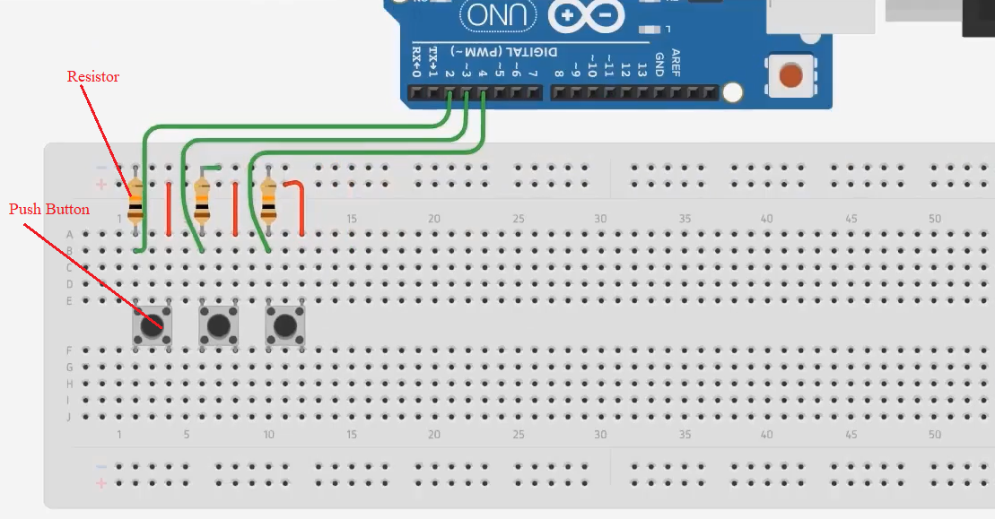
See Figure 3; we used a breadboard, Arduino Uno board, and three pushbuttons. And I will interface the buttons to the Arduino board in a Pull-down configuration.
Button’s one terminal is connected to the Vcc(red color wire indicates the Vcc connections), and another terminal is connected to a resistor, i.e., 10-kiloohm pull-down resistor.
After that, you connect the three buttons to the Arduino board. According to the table(figure 1), button 1 should go to the Arduino PIN 2. Button 2 goes to PIN 3, and button 3 should go PIN 4, as shown in Figure 3.
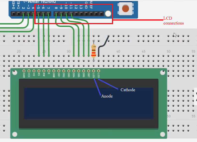
And we also have to take one LCD. Figure 2 table shows the LCD connections. LCD_RS should go to PIN 5. LCD_RW is to PIN 6. The Enable pin of the LCD should go to PIN 7.
After that, we will be using LCD data communication in 4-bit mode. That’s why, in the 4-bit mode, you cannot use the data lines DB0, DB1, DB2, DB3. So, they are not used. DB4 you have to use. DB4 to PIN 8, DB5 to PIN 9, DB6 to PIN 10, DB7 to PIN 11.
The Anode of the LED should go to the Vcc. It has to be through a resistor. Take a resistor (a 220ohm resistor) because it is connected to the internal LED. The power to the LED should go through a resistor connecting it to the Anode. And the cathode of the LED that’s a negative terminal of the LED(the backlight LED) should go to the ground. The black color wire indicates the ground connection.
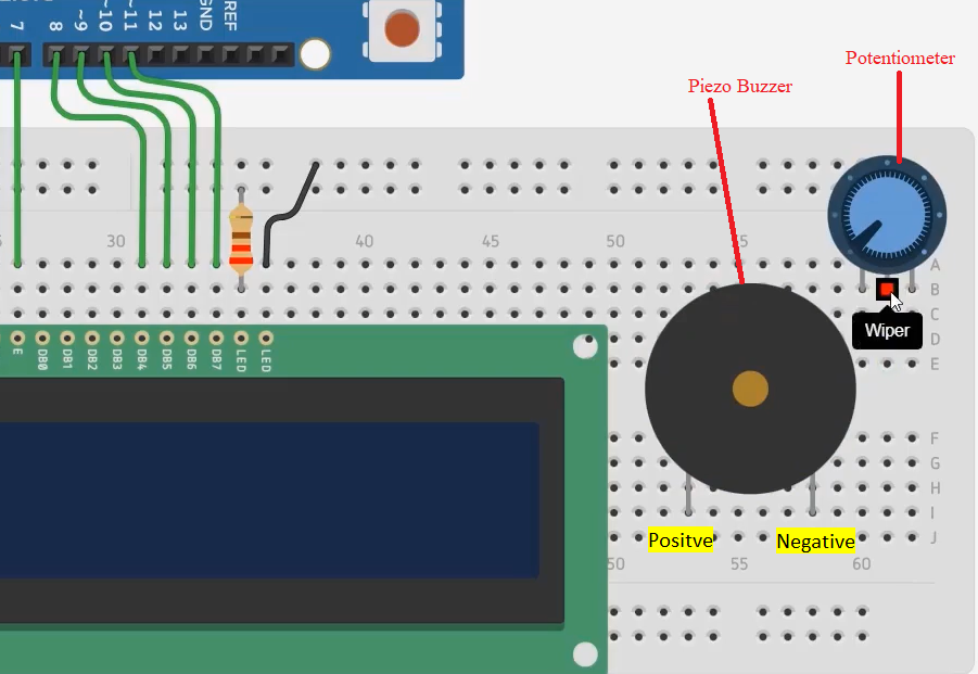
And after that, you also need one Potentiometer. The Potentiometer is around 100kiloohm. This is for the contrast setting of the LCD. And we also need one buzzer(Piezo buzzer).
The wiper must be connected to the contrast pin of the LCD (it is indicated in orange color wire). Terminal 1 of the potentiometer can either go to ground or Vcc. We will give it to Vcc.
If terminal 1 is Vcc, then terminal 2 must be ground. And positive terminal of the buzzer we will give it to PIN 12. And the negative should go to the ground.
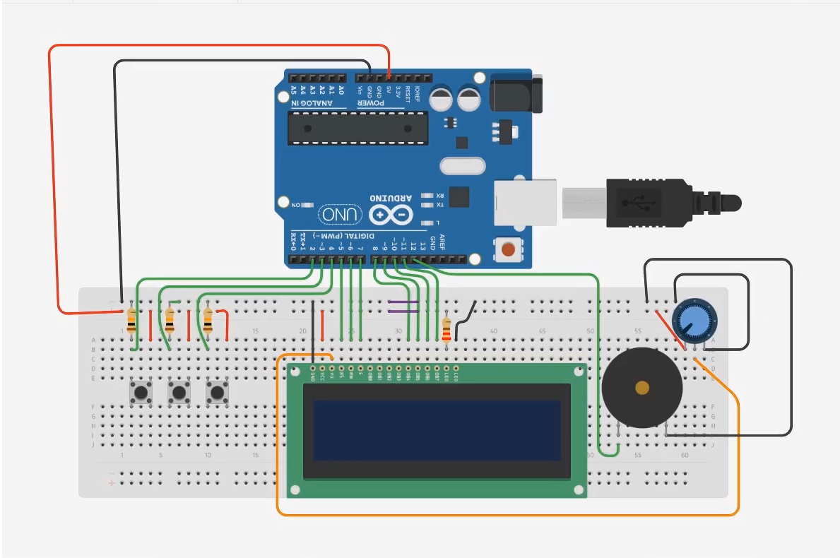
After that, finally, you have to connect the ground of the Arduino board to the ground of the breadboard. And 5 volt to 5 volt rail of the breadboard. The purple wire indicates the power rail’s continued connection of the breadboard, as shown in Figure 6. Those are the connections you have to make.
The code you have written you can paste over here in the text section (as shown in Figure 7), and you can even simulate that.
FastBit Embedded Brain Academy Courses
Click here: https://fastbitlab.com/course1