Exercise-007 Handling TICK event in TICKING state and testing
In this article, let’s send the Tick event to this state machine and update the display in real-time.
Now I will introduce an Internal transition. Figure 1 shows how you draw an internal transition in this tool.
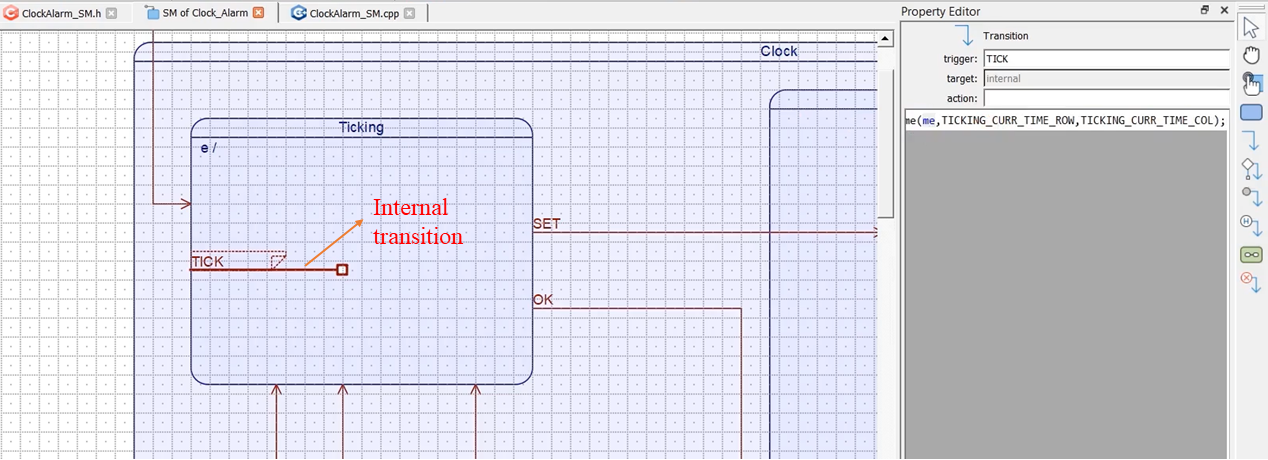
Just select the transition and draw a line. I’ll call this event or signal name ‘TICK.’ You can see that it says the target is internal; the target is not going anywhere else. It is just an internal event or internal transition.
Whenever the TICK event is received, let’s say the TICK event is sent to the state machine for every 50 milliseconds. It should update the display. Whatever you do in the Entry action, you should do it here as well.
Select that internal transition, and you can define some action for that. So, I’ll call the same Clock_Alarm_display_curr_time function.
Clock_Alarm_display_curr_time(me, TICKING_CURR_TIME_ROW, TICKING_CURR_TIME_COL);
Now, let’s test this. Save this and generate the code.
Let’s go back to our code. And from the main.c, we will send that event. Let me define one variable uint32_t tick_time = millis(); I will initialize that to millis(), this must be a static variable.
while(millis() – tick_time >= 50). That is the current time minus the previously saved time. If it is greater than or equal to 50 milliseconds, we will send the TICK event.
void loop() {
// put your main code here, to run repeatedly:
static uint32_t tick_time = millis();


 while(millis() - tick_time >= 50 ){
//send TICK event
tick_time = millis();
Q_SIG(super_ClockAlarm) = TICK_SIG;
QHSM_DISPATCH(super_ClockAlarm);
}
Send the TICK event in main.c
How do you form an event?
So, we did that in the previous exercise. In the last exercise, we should use QHSM_DISPATCH and the signal name we have to store inside this pointer. Let’s do that.
Go to main.c, and here let’s get the pointer of the superclass Q_SIG, Q_SIG of the superclass = TICK_SIG; And QHSM_DISPATCH, use super_ClockAlarm pointer here, as shown above.
Now, this dispatches the TICK signal for every 50 milliseconds. And we should reinitialize this tick_time variable, tick_time = millis();
And make sure that you keep this event producing code in the loop function. Now, let’s test this.
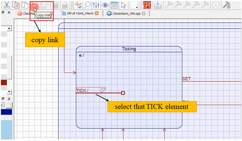
You want to locate the code associated with this TICK element. Here, how do you locate that code?
For example, you should select that TICK element; this is an internal transition. Select that element, and here there is an option copy link, so copy the link, as shown in Figure 2.
And go to your IDE and search here. Paste that, and it takes you to that code block.
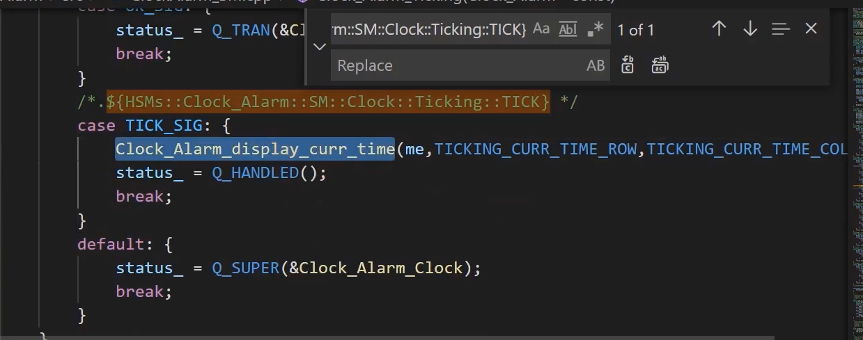
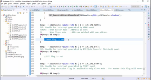
Here you can see that(Figure 3), when we are in Clock_Alarm_Ticking state handler, when the TICK_SIG is received, Clock_Alarm_display_curr_time code will be executed.
Now another problem that I’m facing here is, in the datasheet, the TCCR1B register says the default value is 0. But, it was not the case when I tested it right after the Arduino board reset; it shows the value 3. That means, even though the datasheet says this initial value, the Arduino bootloader code may be changing this register value; it is maybe.
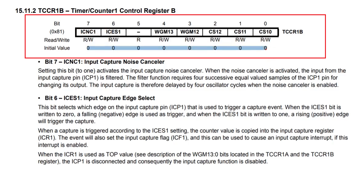
That’s why we will initially reset this to zero, or you write this whole value into the TCCR1B register. Because I thought the initial value of TCCR1B should be 0, but that was not the case.
static void Timer1_setup(void){
   TCCR1A = 0;           //CTC mode
   TCCR1B = B00001100;   //prescaler=256,CTC mode
   TIMSK1 |= B00000010;  //Interrupt enable for OCR1A compare match
   OCR1A = 6250-1;       //OC match value for 100ms time base generation
}
modify the value of TCCR1B register
And I also saw some problems in the code Clock_Alarm_display_curr_time.
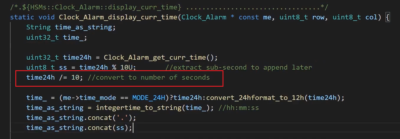
Here the ‘ss’ field is extracted. Actually, we should not divide by 10 here. First, you get the current time (time24h), then extract the sub-second field, and after that, you can convert a number of seconds. Now with these modifications, let’s test on the hardware.
FastBit Embedded Brain Academy Courses
Click here: https://fastbitlab.com/course1