Exercise-007 Drawing an HSM
In the exercise 007ClockAlarm, let’s create a new folder and call it ‘qm.’ Now, we have to keep the new model file, which we will create using the ‘qm’ tool. Let’s launch the qm tool.
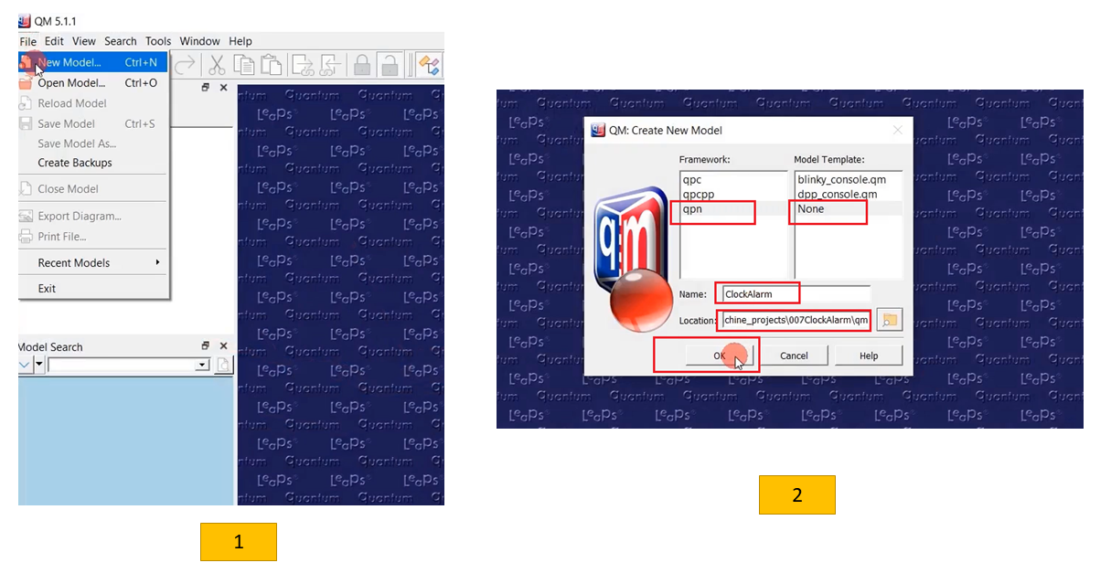
- Go to File and click on New model.
- Select Framework is ‘qpn’ → Model template is None → Name for your project or model; let’s call this ClockAlarm. And provide the path of the ‘qm’ folder. I will open that in the File Explorer to copy this path. Just open that location and select ‘qm,’ and click OK.
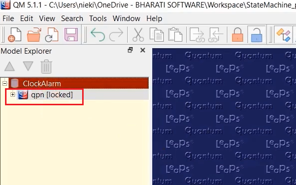
You must see ‘qpn’ as shown in Figure 2.
After that, before creating a state machine model, you must create a package. Right-click over the project ClockAlarm and select Add Package, as shown in Figure 3.
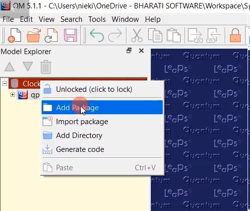
‘Package’ is nothing but it’s a group of different elements, and by means of a package, you can provide a namespace. The project may have different packages. The project may contain any number of packages. And if you have any plan to reuse certain variable names, attribute names, or function names in different packages, you can assign a different namespace.
You can get more information about packages in the Working with Packages – QM user manual, shown in Figure 4.
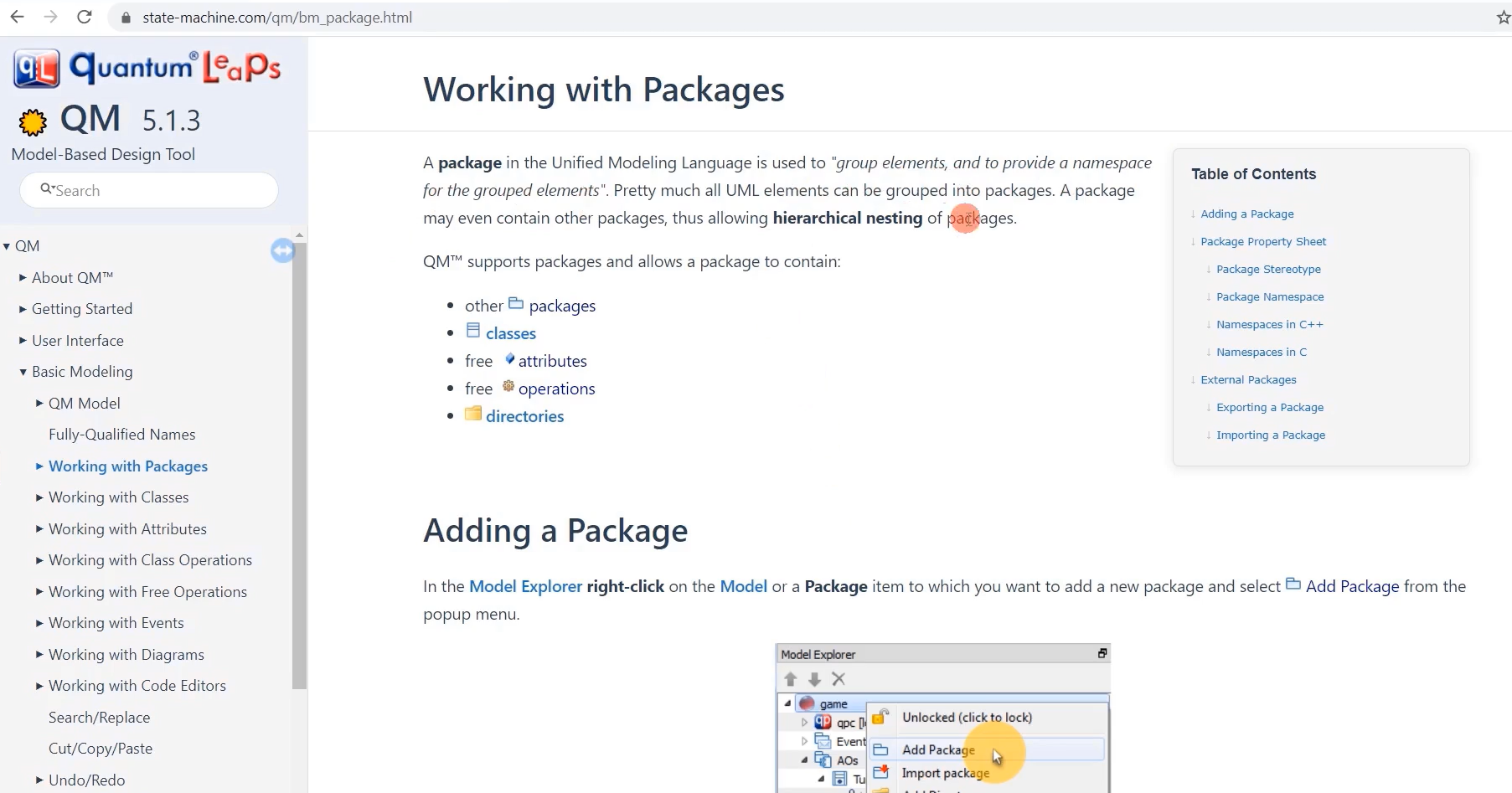
It is used to “group elements, and to provide a namespace for the grouped elements.” A package may contain other packages. Inside the package, you can create classes, create free attributes, and create free operations, directories, etc.

It also provides a namespace option here. You can assign a name for a namespace if you plan to use more than one package.
For the stereotype option, select ‘components’ here.
You can give a name for the package; I’ll provide HSMs ( Figure 5). That’s how you create a package.
Under the package, let’s create a class.
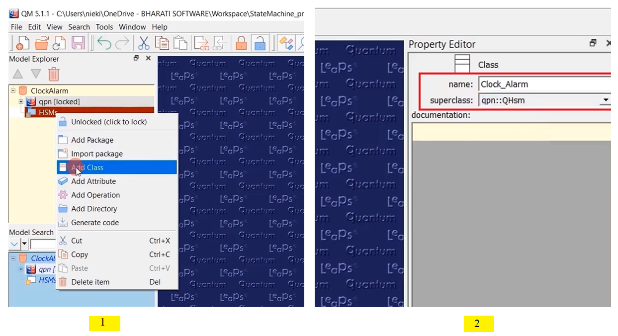
- Let’s click on the package HSMs and select Add class.
- This is our main application structure name; let’s give Clock_Alarm. And select the superclass. The superclass is ‘QHsm.’ So, choose qpn::QHsm. Our Clock_Alarm is derived from QHSM. Then save.(Figure 6)
Now we can create an attribute, as shown in Figure 7.
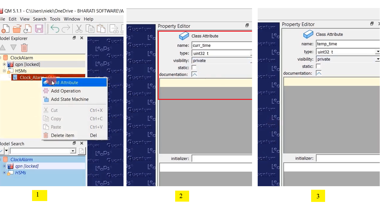
- Click on that Class name and select Add attribute.
- The First attribute is the current time; the type is uint32_t; visibility is private; this is a non-static attribute.
- After that, let’s create one more attribute. Name as temp_time; type is uint32_t; visibility is private. Like that, you create a couple of attributes.
Now also add a directory and add files to keep the generated code.
- Go to your package HSMs. Right-click and select Add directory.
- Let’s give the path for the directory ‘../src’. We are going to keep all our source files in ‘src.’
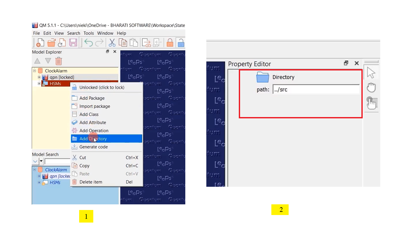
Next, let’s add a file.
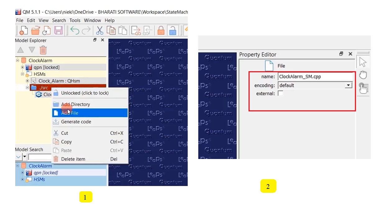
- Right-click on the ‘../src’ directory and select Add File.
- Name the source file as ClockAlarm_SM.cpp; that’s a ‘cpp’ file. And again, add another file, ClockAlarm_SM.h, as shown in Figure 9. Currently, I’ll keep them as internal files.
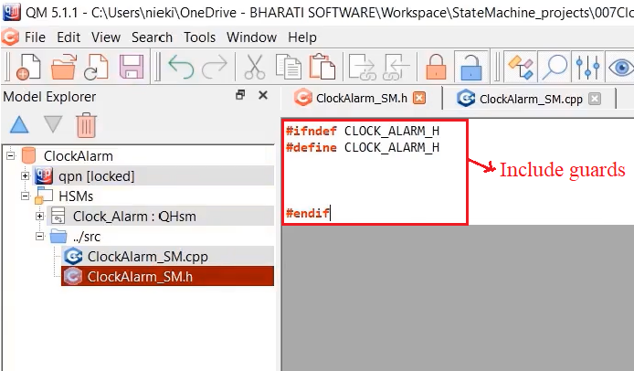
And now, let’s provide the include guards for the header file, as shown in Figure 10.
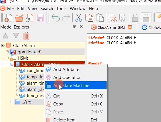
Now, let’s add the state machine. State machine we add to the Class. Right-click on the ClockAlarm, and select Add State Machine.
Double click on SM, you get the canvas to draw your state machine, shown in Figure 12.
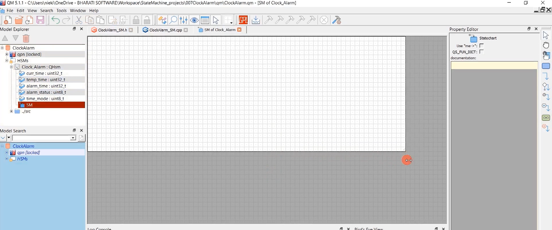
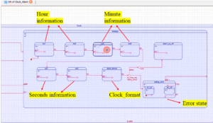
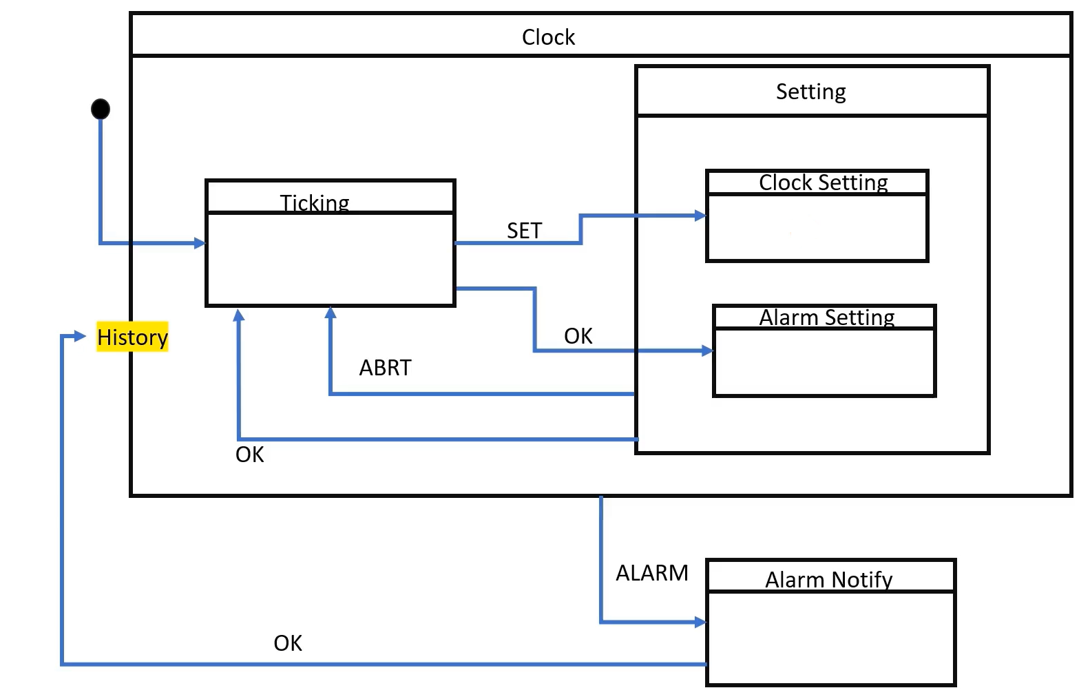
You can draw a state machine like this shown in Figure 13.
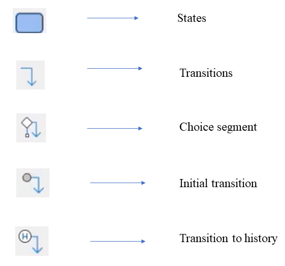
You can get all the required state machine components in canvas, like states, transitions, choice segment, initial transition, etc(Figure 14). Now click on the state; you need to drag anything, click it on canvas. That’s it.
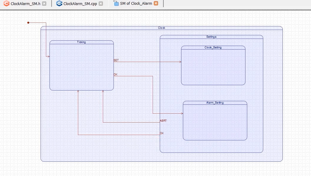
Click on the state, and you can change the name. I’ll call it Ticking, Clock, Settings, Clock_Setting, and Alarm_Setting.
Let’s draw some transitions. First of all, the initial state. When the application starts, the initial state will be ticking. It is already ready-made, the initial transition is available. Just click on this initial transition, and you have to draw.
Now, let’s draw a transition from Ticking state to Clock_Setting state. When the signal ‘SET’ arrives, it should transit to Clock_setting. Just take the transition component and draw. By default, it names it TRIG1; you can select that component and change the name. We’ll use capital letters for all the signals’ SET’. And when ‘OK’ arrives, when the state is Ticking, it transits to the Alarm_setting state. Take the transition component and draw. Name it as ‘OK.’
And you give one superstate ‘Setting,’ then let’s draw ‘ABRT’ from settings state to Ticking. And after that, the transition from the setting state to ticking. Take the transition component, and draw. Name it as OK, as shown in Figure 15.
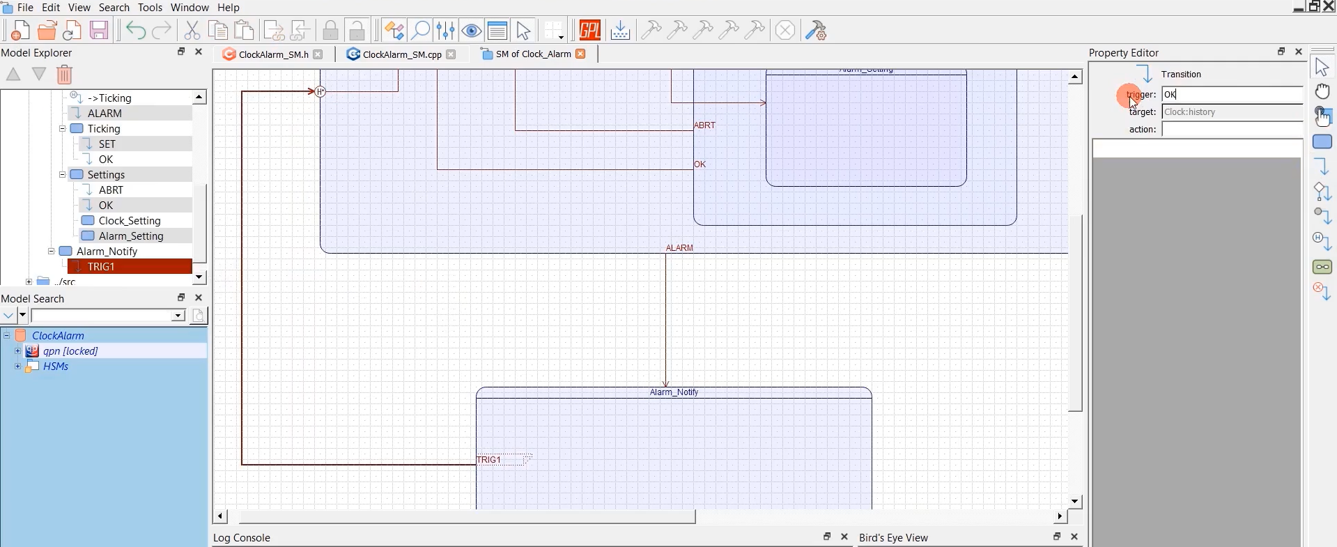
We need one more state for Alarm notification; I will draw that, as shown in Figure 16. And I’ll call this Alarm_Notify, and it happens with the event Alarm.
When it is in the Alarm_Notify state, it will show the notification. It will say to the user, “Hey, Alarm has happened.” So, the user says OK. And when the user presses OK here, it should come back to the Clock state, but it should go to the history state.
Let’s define the history for Clock. We need deep history. History for the clock can be achieved by using a history state on states any of the boundary line. I take the transition to history component, and I put that on the boundary. You have to put that on the boundary.
Transition to history is a history of Clock. If the history is not available, then this is a default transition. This signifies the default transition. And we’ll take one transition from Alarm_Notify to history. I’ll call this OK. Save it. Complete up to here.
FastBit Embedded Brain Academy Courses
Click here: https://fastbitlab.com/course1


