Exercise-007 States, Signals and Data structure used
In the previous article, you just saw the demo of the 007ClockAlarm application. You can imagine a few states in the application by seeing the demo.
Sometimes, the application presents the current time to the user, which I will call a ticking mode or a ticking state of the project. The user can also do a clock setting; that’s why we can introduce one more state called clock setting. And the user can also do the Alarm setting; that’s why we can introduce one more state called Alarm setting.
You can imagine such states or write it down on paper before modeling through the software.
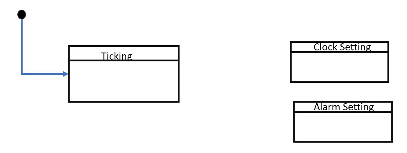
The ticking state is our initial state. Whenever you give power to the application, our application will be in ticking mode, showing the current time to the user.
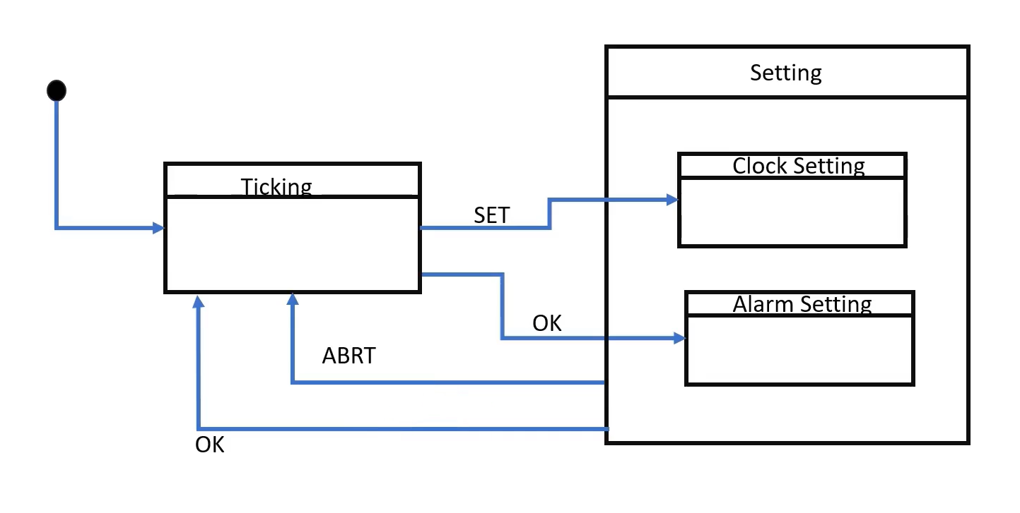
- When the application is in ticking mode, if the user presses the button SET, the application state changes to the Clock setting. Because the user wants to do Clock setting.
- And whenever the application is in ticking mode, if the user presses the button OK, then the application’s state changes to the Alarm setting.
That’s why there are two events. When the application is in ticking mode, the ‘SET’ and ‘OK’ events or signals are processed like that.
- When the application is in Clock setting or Alarm setting mode, the user can Abort the setting at any time. That’s why we can also give one transition from setting modes to the ticking mode.
Instead of drawing individual Abort, you can draw a superstate for these two states, and you can give one common transition from the setting state to the ticking state. So, that’s the Abort, as shown in Figure 2.
- And also, we can give one more transition from the setting state to the ticking state if a user is done with the setting, then the user can come back to the ticking mode. So, the only difference between ‘Abort’ and ‘OK’ is here the setting is approved; that is, the setting is saved. Here it is not saved, it is Abort it.
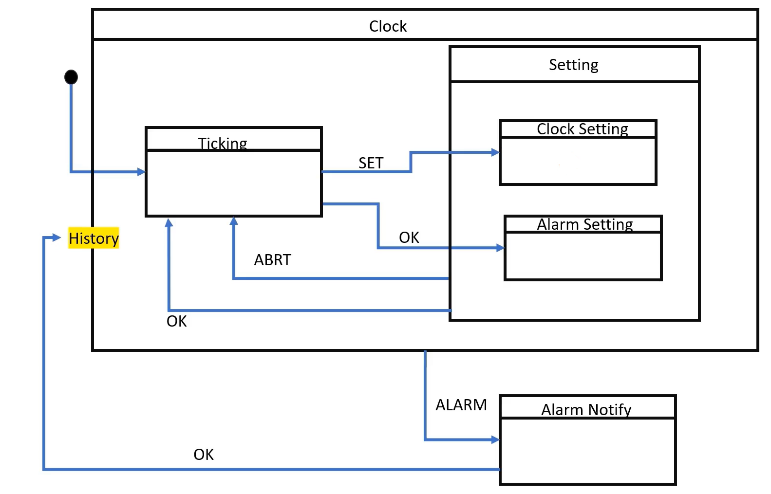
After that, we can create one more super state for all these states; let’s call it a superstate Clock.
And we can introduce one more event or signal called ALARM, which takes us to the Alarm notify state because Alarm can happen at any place. It can happen in a ticking state; it can happen while you are doing the Clock setting or while you are doing the Alarm Setting. Instead of giving three transitions from ticking state, clock setting state, and Alarm setting state, you can create one superstate called Clock, and then you can give one common transition from Clock superstate to Alarm Notify state. That is for the ALARM signal.
When the application is in the Alarm notification state, it can show the Alarm notification to the user; you just saw that in the demo. And whenever users press the button OK, the Alarm notification ends, and the application now goes back to the history of this Clock state.
Because, when Alarm took place, the user might be doing some Clock setting or Alarm setting or something. That’s why it makes sense to come back to the history state. I hope that makes sense. And inside the Clock setting, we have to draw some more sub-states to configure the hour information, minutes information, seconds information, and other things, which we’ll see later.
Look at Figure 3; this is just a zoomed-out picture of our whole state machine.
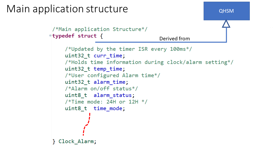
We have to create one main application structure, for which we are drawing the state machine. And this main application structure is derived from QHSM because this is a hierarchical state machine. That’s why we will derive our structure from QHSM, as shown in Figure 4.
And let’s introduce a couple of attributes to the main application structure. The current time attribute is used to hold the current time (real-time). So, the curr_time variable is updated by the timer ISR for every 100 milliseconds. We have to implement a one timer ISR, which we’ll see later. The state machine never updates the curr_time variable. The timer ISR only updates this.
There will be one more variable called temporary time (temp_time). This is used to hold the setting time. While you are doing some settings, settings information will be stored in a temporary time. Temporary time will be copied to the current time only during approval. That is, when you say ‘OK,’ otherwise, it is not copied like that.
Alarm_time holds the user’s Alarm information.
And there will be one more variable called alarm_status, which holds whether the alarm is ON or Off, that is active or deactivated state.
And also, the user can select a different time_mode, like, the time can be represented to the user in 24-hour format or 12-hour format. That information, that is a user selection is stored in the time mode variable.
And there could be some other variables or other attributes we may be using while drawing the state machine, so we’ll see that later.
If you want more attributes, we will keep adding those attributes to this structure. Currently, I can think of only these attributes.
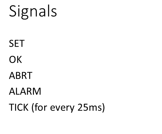
These are the signals you saw in the previous picture of a state machine. I will use SET, OK, ABRT, ALARM, and there will be a TICK event sent to the state machine for every 25 milliseconds.
This TICK event we can use to update the display or if you want to blink some warning messages, error messages, alarm notification messages, so we can make use of the Tick, which is posted to the state machine for every 25 milliseconds.
These are the same LCD files that we used in the previous exercise. You download it and copy it into the source folder of the VS code project.
FastBit Embedded Brain Academy Courses
Click here: https://fastbitlab.com/course1