I2C Introduction and difference with SPI
I2C Introduction
The I2C (inter-integrated circuit) bus interface handles communications between the microcontroller and the serial I2C bus.
In other words, I2C is just a protocol to achieve serial data communication between integrated circuits which are very close to each other. It provides excellent support to the slow devices.
Structure of the I2C bus system

For example, EEPROM, ADC, and RTC, etc.
I2C is not only used with the single board but also used with the other external components which have connected with boards through the cables. I2C protocol details like how data sent, how data should receive, how handshaking should happen between the sender and receiver, error handling is more complicated than the SPI protocol. So, in other words, SPI is a straightforward protocol compared to I2C.
Difference between SPI and I2C protocol:
I2C and SPI are both bus protocols that allow short-distance, serial data transfer. I2C originates from the Philips semiconductor division, while Motorola created SPI. In electronic devices like smartphones, TVs, and laptops to control peripherals like power management chips, input devices, and DACs both protocols are commonly used.
Specification:
- I2C is based on dedicated specifications. NXP designs the specifications.
- For SPI there are no such specifications, but TI and Motorola have their specifications.
Multi-master capability:
- I2C is multi-master capable, whereas SPI has no guidelines to achieve multi-master capability.
- In SPI, multi-master capability depends on designers or vendors.
For example, STM SPI uses multi-master capability, but the software code will handle the arbitration between multiple masters. But the arbitration in I2C is automatically taken care of by hardware.
Acknowledging:
- I2C hardware automatically acknowledges every byte received.
- But SPI does not support any automatic acknowledging.
Pins:
- I2C needs just two pins for communication.
- Whereas SPI may need four pins or even more than that if multiple slaves are involved in communication.
Figure 1 shows the I2C pin structure. That is SCL(serial clock) and SDA(serial data). So, I2C needs two pins to connect all slaves and masters, and that is one of the most significant advantages of the I2C.
Addressing:
- I2C master talks to slaves based on the slave address. So, the I2C protocol is address-based communication.
- In SPI a dedicated pin is used to select the slave that is c as SS(slave select) pin. So, SPI does not support address-based communication.
Communication:
- The I2C protocol is inherently half-duplex, while the SPI protocol is inherently full-duplex. SPI also uses half-duplex.
Speed:
- For I2C the maximum speed is 4MHz, possible only in ultra speed plus mode of the I2C peripheral. Most of the microcontrollers will not support the ultra-speed plus mode. For example, the maximum speed of most of the ST microcontroller is just 400KHz or 1MHz, not more than that.
- For SPI, the maximum speed is it’s peripheral clock divided by 2(Fpclk/2). For example, if the peripheral clock is 20MHz, then SPI speed is up to 10MHz. So, SPI is very, very fast compared to I2C.
Slave’s control over serial clock:
- In I2C, the slave can make master wait by holding clock down if ‘it’s busy, this is called a clock stretching feature of I2C. By using the clock stretching feature, the slave can put the master into a wait state, and this happens by pulling the clock to the ground state by the slave.
- In SPI, the slave has no control over the serial clock programmers may use their tricks to overcome this situation.
Data rate:
- Data rate is nothing but number bits transmitted from sender to receiver in one second is very much lesser in I2C compared to SPI.
- SPI is fast compared to I2C. That is the most significant advantage of SPI.
For example, in STM32F4xx, if the peripheral clock of 40MHz then in I2C data rate is 400Kbps and an SPI data rate is 20Mbps. So in this scenario, SPI is 50 times faster than I2C.
Some of the terminologies in I2C protocol:
- Transmitter: The device which sends data to the bus.
- Receiver: The device which receives data from the bus.
- Master: The device which initiates a transfer, generates clock signals, and terminates a transfer.
- Slave: The device addressed by a master.
- Multi-master: More than one master can attempt to control the bus at the same time without corrupting the message.
- Arbitration: In the case of a multi-master, the arbitration is required where more than one master is tried to communicate with a slave simultaneously. In I2C arbitration is achieved by the SDA line.
- Synchronization: Procedure to synchronize the clock signals of two or more devices.
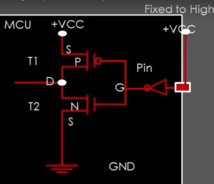
In this article, let’s also discuss SCL and SDA signals. From the Figure 1, both SDA and SCL signals are bidirectional lines and SDA, and SCL signals are connected to the positive supply voltage via pull-up resistors. When the bus is free, both the lines are held at high. The output stages of the devices connected to the bus must have an open drain or open collector configuration. The bus capacitance limits the number of interfaces connected to the bus.
In the following article, let’s learn I2C modes.


