Implementation of I2C init API: Part 3
Configure the CCR register: Let’s do CCR calculations to configure the CCR field.
- Initialize a variable to store the CCR value.
- Determine whether the mode is a standard mode or a fast mode by checking the serial clock speed given by the user. If the serial clock’s speed is lesser than or equals to standard mode speed, configure for standard mode. Otherwise, configure for the fast mode (Figure 1).

i. For standard mode:
- Configure the 15th bit of the I2C_CCR register to 0. No need to configure this because this value is 0 by default.
- Calculate the value of CCR on behalf of standard mode frequency. Figure 2 shows the formula for calculating the CCR in standard mode.

If Thigh = Tlow, then the formula in Figure 2 can be reduced into:
TSCL = 2CCR x TPCLK1
Where TSCL = Thigh + Tlow
CCR = TSCL / 2TPCLK1
For frequency domain, TSCL = FSCL and TPCLK1 = FPCLK1, now the above formula becomes CCR = FPCLK1 / 2 X FSCL
To calculate the CCR we have to use the formula of frequency domain, as shown in Figure 3.

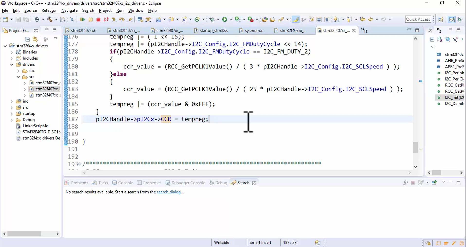
- Program the CCR value and store it in the tempreg variable. Since the CCR field is of 12-bits, mask out all other bits except the first 12 bits using a bitwise & operator, as shown in Figure 4.

ii. For fast mode:
- Set the mode to fast mode by configuring the 15th bit of the I2C_CCR register to 1 (Figure 5).

- Program the duty cycle in the 14th bit (or DUTY field) of the I2C_CCR register (Figure 6) because there are two types of duty cycles supplied by the application.

- Let’s calculate the CCR value for the fast mode. Before calculating the CCR value, remember that there are two different formulas:
a.If DUTY=0 that means the Tlow is 2 times the Thigh, then use the below formulas:
Thigh = CCR x TPCLK1
Tlow = 2 x CCR x TPCLK1
Therefore, CCR = FPCLK1 / 3 x FSCL
b. If DUTY=1 that means the Tlow is 1.7 times the Thigh, then use the below formulas:
Thigh = 9 x CCR x TPCLK1
Tlow = 16 x CCR x TPCLK1
Therefore, CCR = FPCLK1 / 25 x FSCL
Calculate the CCR value depending on the value of the Duty cycle, as shown in Figure 7.

- Program the CCR value and store it in the tempreg variable. Since the CCR field is of 12-bits, mask out all other bits except the first 12 bits using a bitwise & operator, as shown in Figure 8.

- At the end, store the tempreg value into the CCR register, as shown in Figure 9.

FastBit Embedded Brain Academy Courses,
Click here: https://fastbitlab.com/course1


