Implementation of I2C init API: Part 2
The ack control bit is already configured in the I2C_Init function. Now, the next step is to program the CR1 register, as shown in Figure 1.

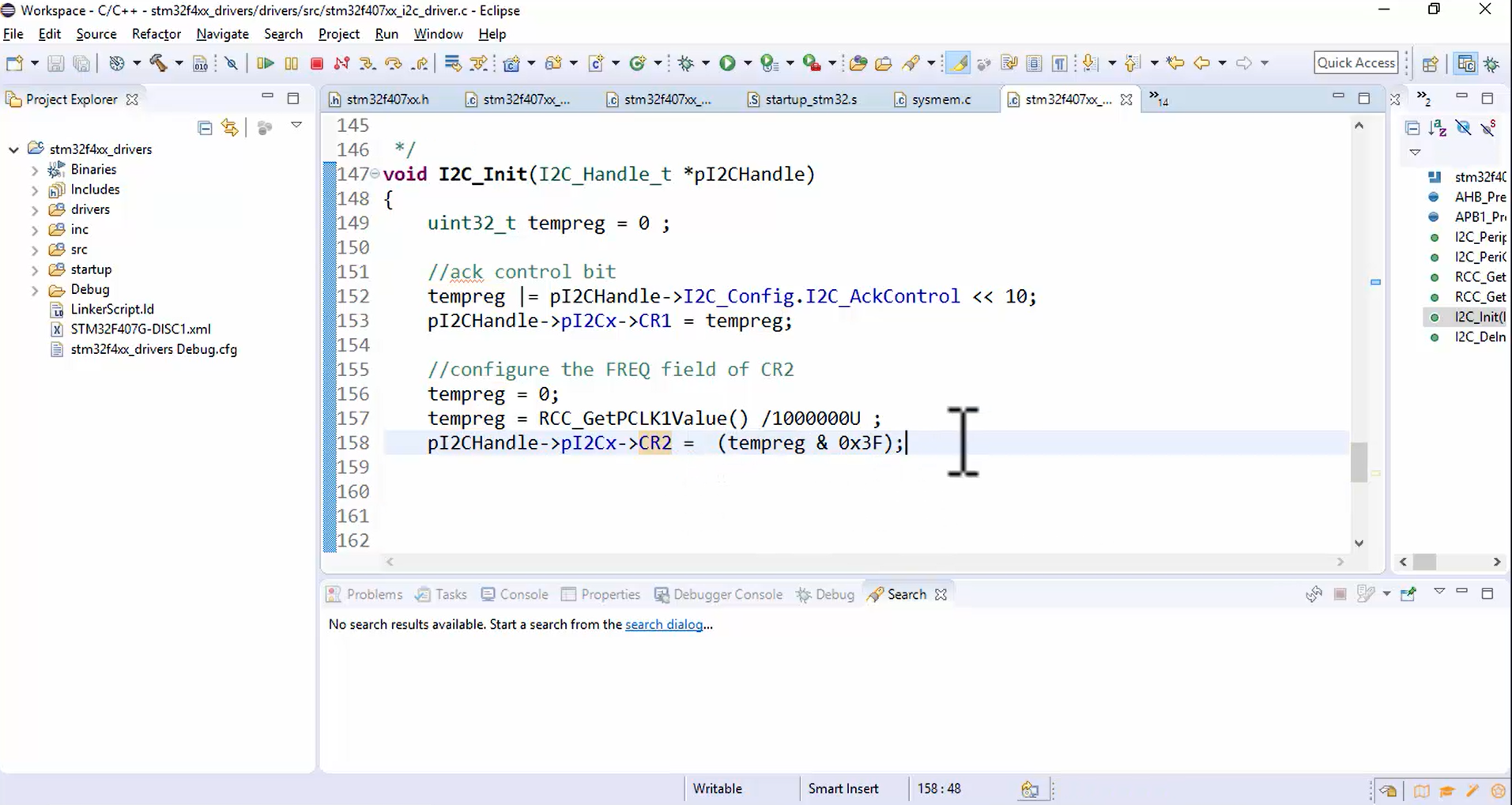
Now let’s configure the FREQ field of the CR2 register, as shown in Figure 2.
- Initialize tempreg = 0.
- Store the PCLK1 value into tempreg using tempreg = RCC_GetPCLK1Value () / 1000000U. Here the PCLK1 value is divided by 1000000U because we need only value 16, not entire value 16MHz.
- Store the value of tempreg into the CR2 register. pI2CHandle -> pI2Cx -> CR2 = (tempreg & 0x3F). The bitwise & will mask all other bits except the first 5 bits of the CR2 register.
Store the slave address in the OAR1 register: OAR1 stands for Own address register 1. The 7-bit slave address must be stored in the 1-7 bits of OAR1 register shown in Figure 3.
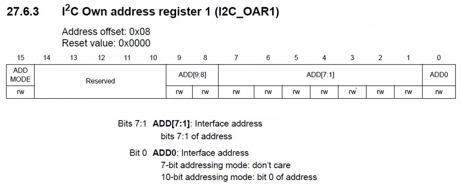
Look at Figure 3. Bit 0 is ADD0, the interface address. It is the 0th bit of the slave address if the slave address mode is 10-bit. Remember that I2C allows the slave address of 10-bit, but generally, the slave address is 7-bit. For the 7-bit addressing mode, the ADD0 field is not applicable. You have to store the address in ADD [7:1] field.
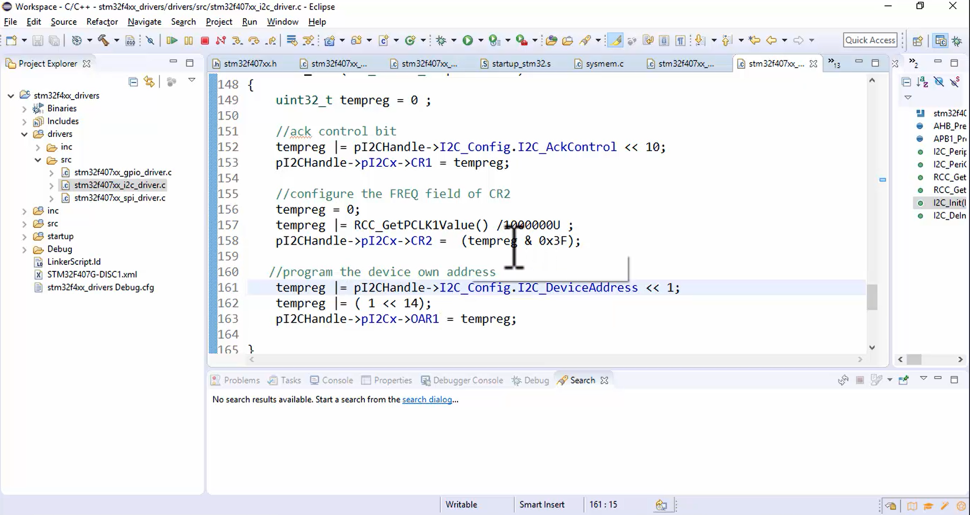
Now let’s program the device’s own address, as shown in Figure 4.
- Store the device address into tempreg variable using pI2CHandle -> I2C_Config.I2C_DeviceAddress << 1. The device address must be shifted by one because the slave address should not occupy the ADD0 field since it is a 7-bit addressing mode.
- Store the tempreg value into a OAR1 register. pI2CHandle -> pI2Cx -> OAR1 = tempreg.
The 15th bit of the OAR1 register is used to select the addressing mode (Figure 3). If the value is 0 (which is true by default), then only a 7-bit address will be acknowledged, a 10-bit address will not be acknowledged. Whereas while using the 10-bit addressing mode, the ADDMODE field must be set to 1.
In the reference manual, it is given that the reserved bit 14 should always be kept at 1 by software. Let’s do that by using tempreg |= (1 << 14), as shown in Figure 4.
Implementation of I2C init API: Part 3 is continue in the following article.
FastBit Embedded Brain Academy Courses,
Click here: https://fastbitlab.com/course1