Input configuration of Microcontroller’s GPIO Pin
In this article, let’s first decide the mode of GPIO as input, output, or an analog.
If the GPIO pin is in input mode, it can be configured to issue an interrupt to the processor.

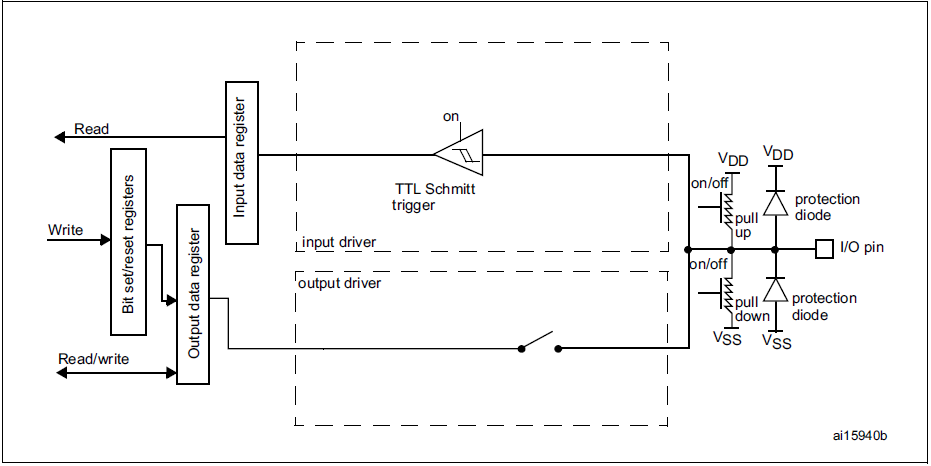
When the GPIO pin (Figure1. I/O pin) configured as in input mode, the Output driver is disabled, and only the Input driver is enabled.
The I/O state of the pin will be read to Input data register for every AHB1 clock cycle because GPIO’s connect over the AHB1 bus. For every one cycle of the AHB1 bus, the I/O pin state will be read. And the Input data register will be updated, and from there the firmware can read the values of the GPIO pin state.
By default, the Pull-up and Pull-down register deactivated.
In input mode, the output driver is deactivated, which means an open circuit. So any random noise of the microcontroller can affect the value which is being read by the input data register. That means whatever the data read from the I/O pin may not be correct.

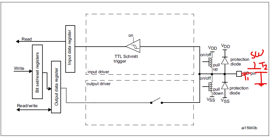
Let’s connect a switch to the I/O pin that means terminal T1 of the switch connected to I/O pin and terminal T2 of the switch connected to the ground. And by default, pull-up and pull-down resistors are not there.
So, when the switch closes, the I/O pin will be shorted to the ground. That means I/O pin will be 0, and the value will sample for every AHB1 clock cycle. And it will be updated automatically by the microcontroller into the input data register. So, the input data register will read the value 0.
When the switch is open, the I/O pin neither grounded nor connected to the proper voltage. Because of the circuit noise, there will always be fluctuation of voltage at the output pin. So, for every AHB1 clock cycle, the state of the I/O pin will not be 0 or 1, it will keep changing. Thus, the input data register keeps changing its value due to the circuit noise.
To solve this issue, you have to activate the pull-up resistor either internally or externally. Let’s enable an internal pull-up resistor, and the switch is open, here I/O pin is not floating because the I/O pin held at VDD. So, the input data register will read the value 1.
So, while using I/O pin in input mode, give importance pull-up resistor.
In the following article, let’s see Output configuration of GPIO Pin in push pull mode.
FastBit Embedded Brain Academy Courses,
Click here: https://fastbitlab.com/course1


