LTDC layers initialization
The LTDC (Layered Transmission Display Controller) is a hardware component commonly found in embedded systems and graphics display controllers. It allows for the simultaneous display of multiple layers of graphics, text, and other visual elements on a single display.
In an LTDC system, each layer is represented by a separate framebuffer, which contains the pixel data for that layer. The LTDC controller then combines the pixel data from each layer according to a set of blending rules to create the final output image that is displayed on the screen.
LTDC layers Initialization steps:
- LTDC supports 2 layers
- You can active either of the layers or all layers as per your application need
- Programmable default color settings for each layer
- Programmable frame buffer address settings for each layer
- Flexible blending options(Constant and pixel alpha blending)
- Programmable window positioning for each layer
- Most LTDC layer registers are shadow registers, and you need to activate loading shadow values to real registers explicitly.
Essentially, layers in LTDC refer to frame buffers, representing different visual elements or graphics that can be displayed simultaneously.
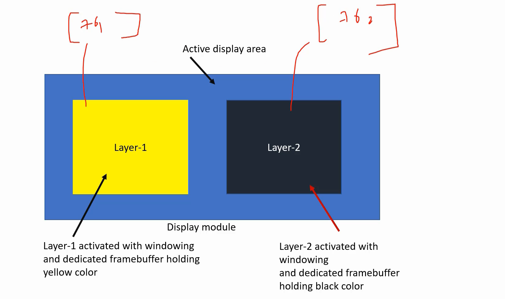
For example, there are two layers that display two different colors. Layer 1 has its own frame buffer in the memory, and Layer 2 also has its own frame buffer in the memory. This means that you can simultaneously use two frame buffers and display different pixel values, images, colors, and so on.
Moreover, with the concept of layers, you can control the width and height of each layer. Additionally, you can position a layer wherever you desire by utilizing the horizontal offset, vertical offset, and other related parameters. Each layer is equipped with its own set of configuration registers, allowing you to adjust these settings accordingly.
To use a layer successfully, there are some points you need to remember. The first thing is you have to properly configure the blending options.
Layer and Blending
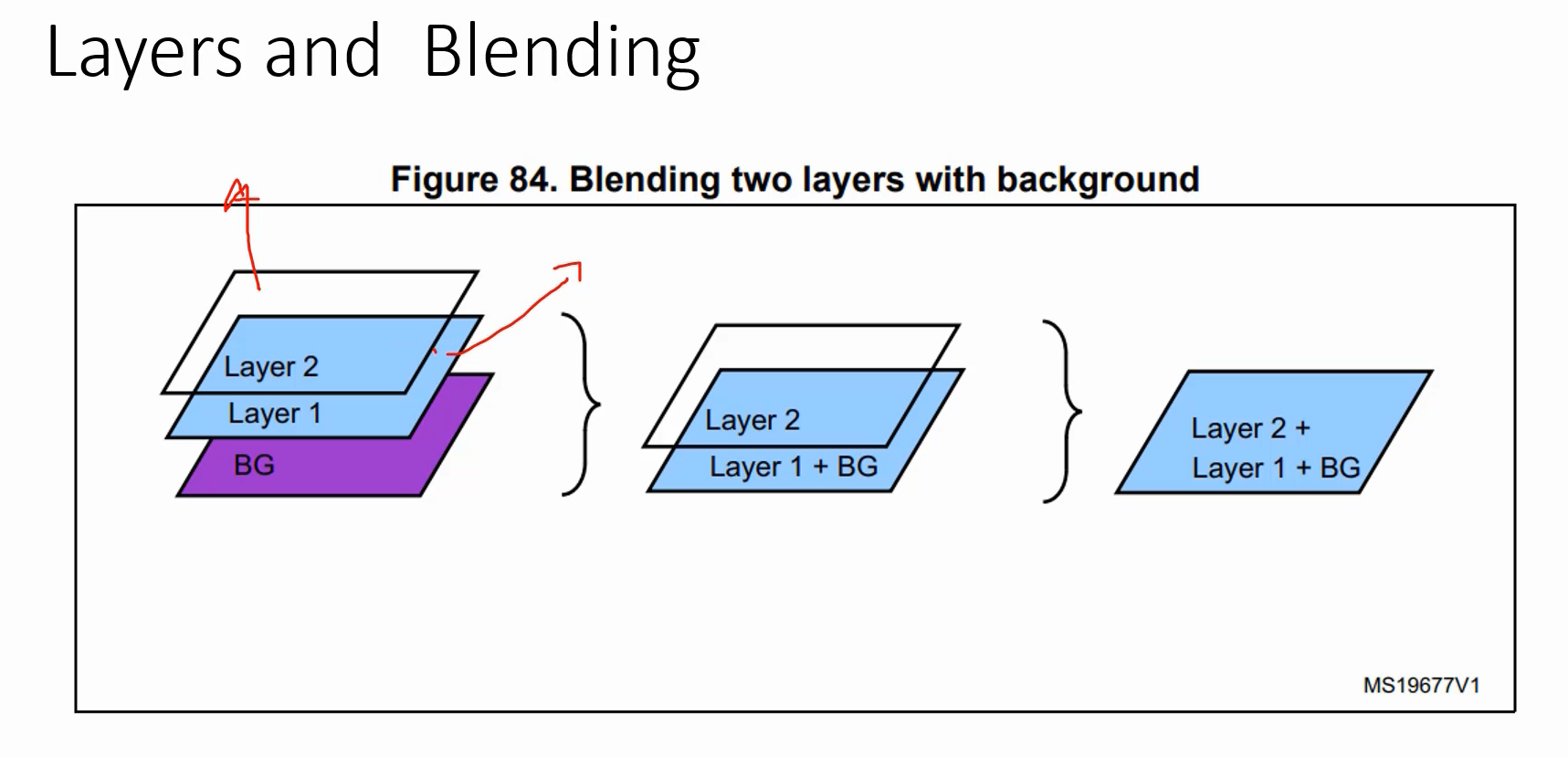
I have obtained the diagram below from the reference manual of the STM32F4 microcontroller. When both layers are activated, the following is the order in which the layers will be displayed on the screen, as depicted in Figure 2.
Firstly, there will be a background color, and layer 1 will be positioned above it, followed by layer 2. It is not possible to modify this order. Each layer will have its own blending option.
Blending is the process of combining the various layers of the LTDC compression technique to create a final, compressed version of the video frame. The blending process involves using mathematical algorithms to combine the information from the different layers in a way that optimizes the quality and compression of the final image.
Example:
Let’s consider a project, where you have activated only Layer-1. For Layer-1, you have its own frame buffer and let’s say the frame buffer contains pixels to represent rgb(0, 0, 128). It’s kind of dark blue color.
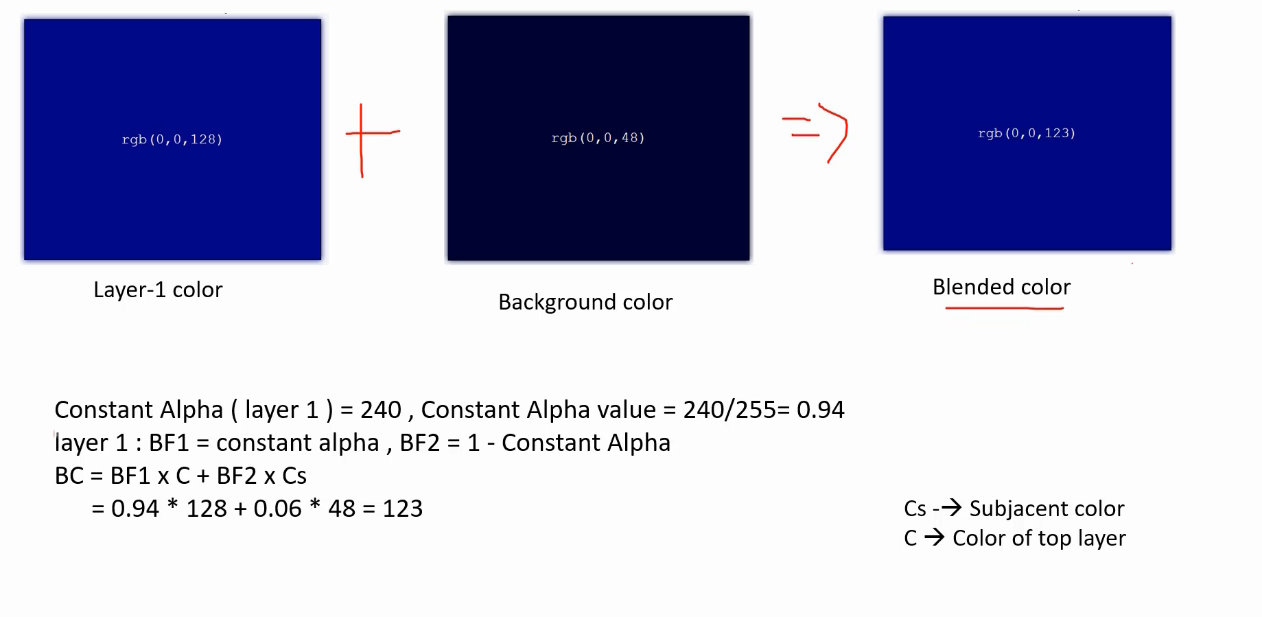
rgb(0, 0, 128) is Layer-1’s color. And rgb(0, 0, 48) is the background color.
The Layer-1 will blend with the background color to produce blended colors. For instance, rgb(0, 0, 123) is an example of a blended color. You can control this blended color by adjusting the constant alpha configuration item of Layer-1.
LTDC layerx control register
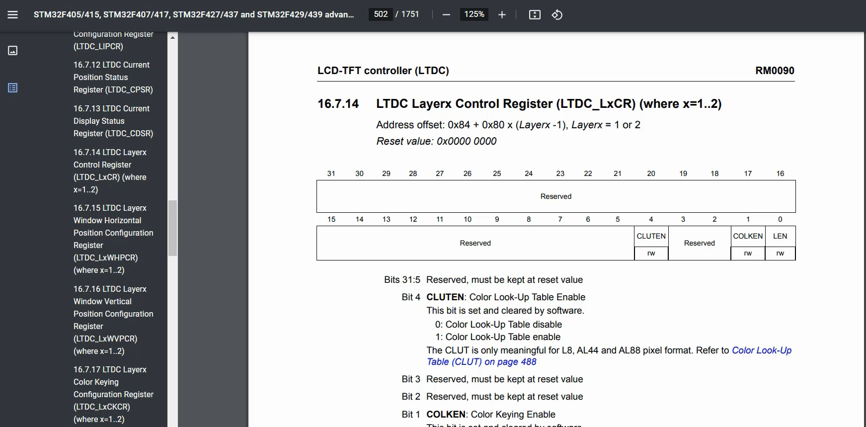
If you refer to the reference manual and navigate to the LTDC registers, explore the layer registers. Whenever you encounter Lx, it corresponds to the layer register. ‘x’ may be 1 or 2, because there are two layers.
LTDC Layerx Constant Alpha Configuration Register
The LTDC Layer x Constant Alpha Configuration Register allows you to control the opacity of a layer. The maximum value for this field is 255.
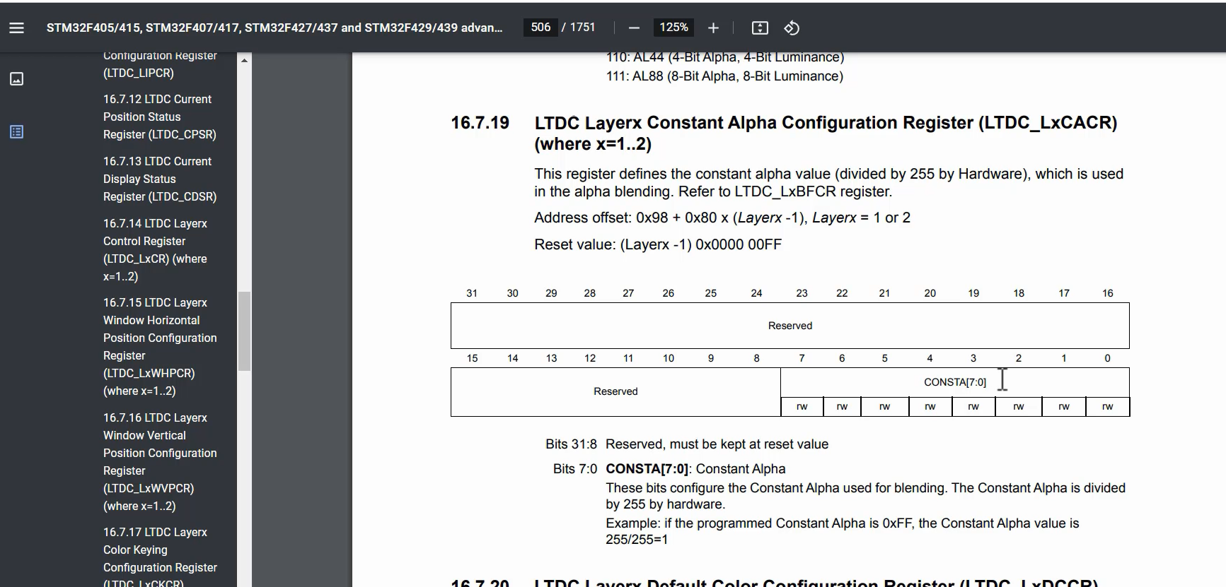
When you set the constant alpha of Layer-1 to 255, it means that Layer-1 is fully opaque to the background.
Now, let’s consider a scenario(Figure 3) where the constant alpha of Layer-1 is set to 240. In this case, the LTDC will calculate the constant alpha value by dividing the constant alpha value of 240 by 255, resulting in 0.94. The blending process occurs using the following equation: BC = BF1 x C + BF2 x Cs.
BF1 represents the calculated value of 0.94, multiplied by C, C denotes the color of the top layer (Layer-1), that is 128.
That means 94% of the top layer will be used + 6% of the subjacent layer. Cs or the color beneath this layer, that is the background color. 6% of the background color is used to get the blended color 123. So, the LTDC will start transmitting this color. That’s why you can control this proportion using this constant alpha value.
It’s important to note that blending always occurs in the following order: background color (BG) → Layer1 → Layer2. When all the layers are enabled, the final color will be a combination of Layer 2, Layer 1, and the background color.
Layer windowing
Layer windowing refers to the ability to define and manipulate multiple layers or regions on a display screen. The LTDC is a peripheral commonly used in microcontrollers or systems-on-chip (SoCs) to control and drive LCD or TFT display panels.
Layer windowing allows you to divide the display screen into multiple independent regions or layers, each with its own content and properties. This capability is particularly useful when you want to display different graphics, images, or videos in different parts of the screen simultaneously or overlay them on top of each other. For example, you may want to show a background image or video while displaying some dynamic data or graphical elements on top of it.
The LTDC typically supports multiple hardware layers, each associated with a specific framebuffer in memory. Each layer has its own configuration, such as position, size, transparency, and blending options. By configuring these parameters, you can control how each layer is displayed on the screen and how it interacts with other layers.
You need to set the appropriate horizontal offset, vertical offset, layer width, and layer height. Make sure to properly configure these values in the LTDC_LxWVPCR, LTDC_LxWHPCR, and LTDC_LxWVPCR registers.
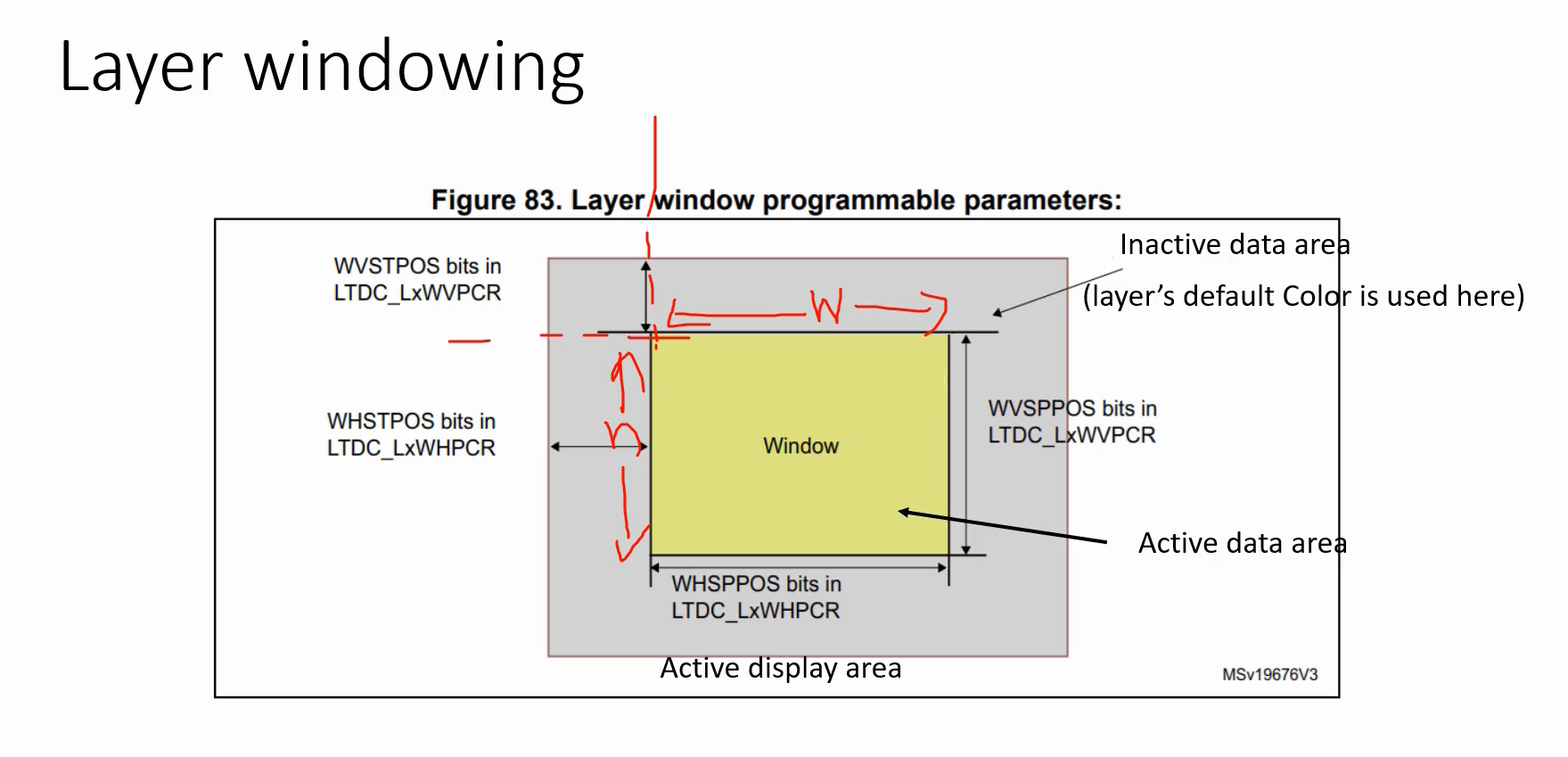
Everything is mentioned in the reference manual.
Let’s begin with the first register: the LTDC Layer Control Register.
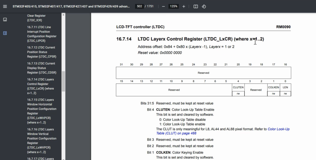
Currently, you can only use this register to enable the “LEN” (layer enable) feature. So, the layer should be enabled by using this bit, otherwise, it will not work.
LTDC Layerx Window Horizontal Position Configuration Register
The horizontal positioning you can configure by using this register is shown in Figure 8.

LTDC Layerx Window Vertical Position Configuration Register
For vertical positioning, you can use this register is shown in Figure 9.

LTDC Layerx Pixel Format Configuration Register
The pixel format for the layer, which you can configure using this register is shown in Figure 10.

LTDC Layerx Constant Alpha Configuration Register
This is the place where you can set the constant alpha value. Each layer has its own default color, which is black because its value is zero. However, you have the flexibility to configure a different color if desired.
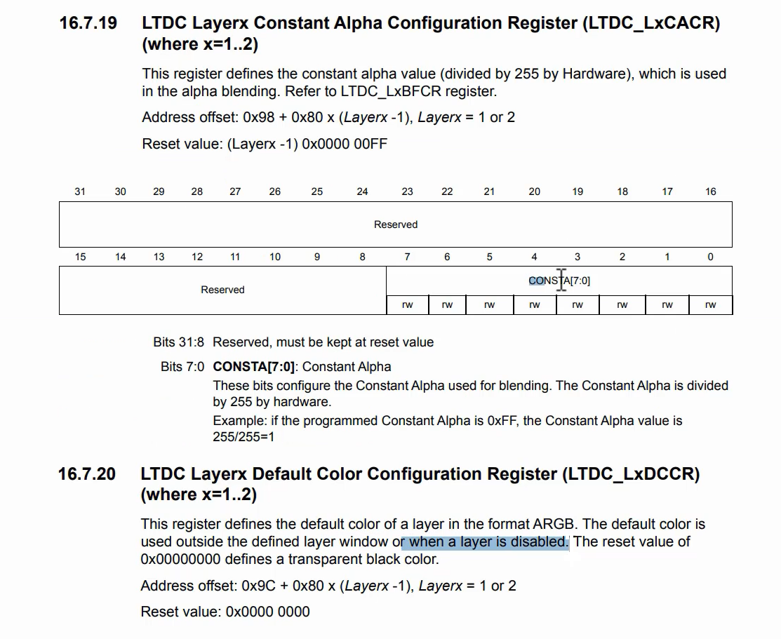
Here it shows, the default color is used outside the defined layer window or when a layer is disabled.
LTDC Layerx Blending Factors Configuration Register
The LTDC Layerx Blending Factors Configuration Register defines the blending factor and is also one of the crucial registers that require configuration.
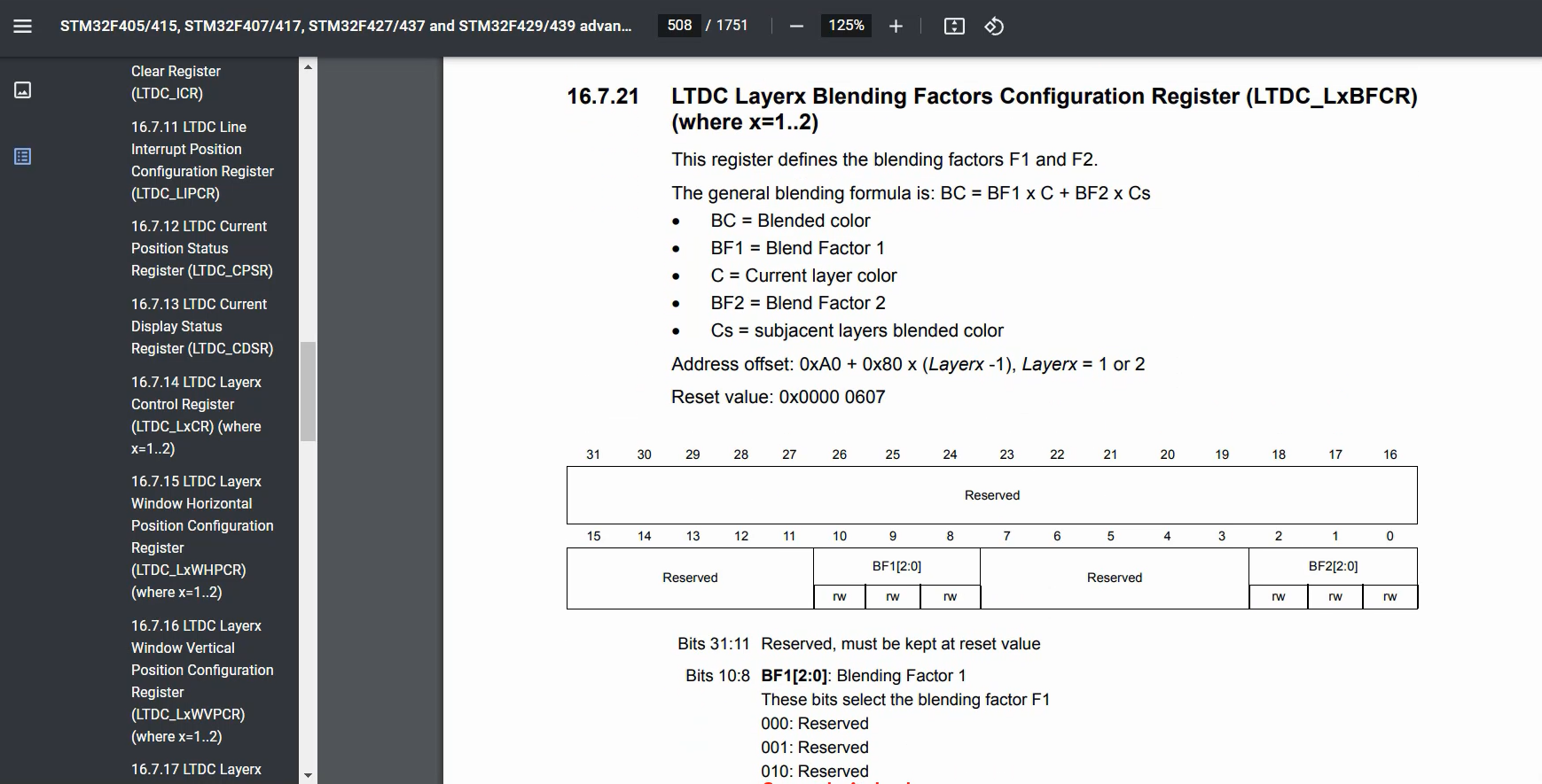
LTDC Layerx Color Frame Buffer Length Register
You can configure the framebuffer address register here.
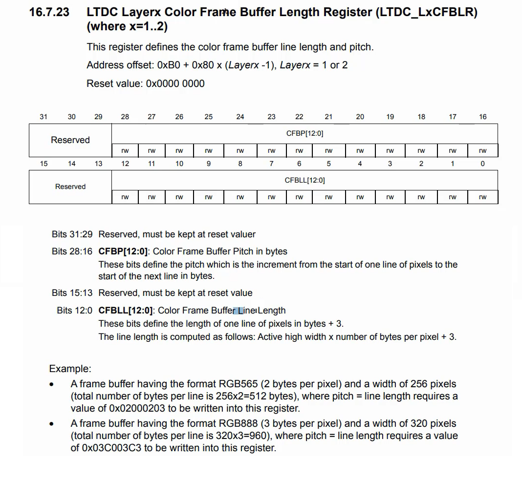
This register defines the color frame buffer line length and pitch.
Pitch is specified in bytes and is the increment from the start of one line of pixels to the start of the next line. These bits define the pitch value.
To calculate the line length, add the length of one line of pixels in bytes and add 3. Therefore, you need to add 3 to this value.
LTDC Layerx ColorFrame Buffer Line Number Register
The number of lines of the frame buffer should be configured in Layer ColourFrame Buffer Line Number Register.
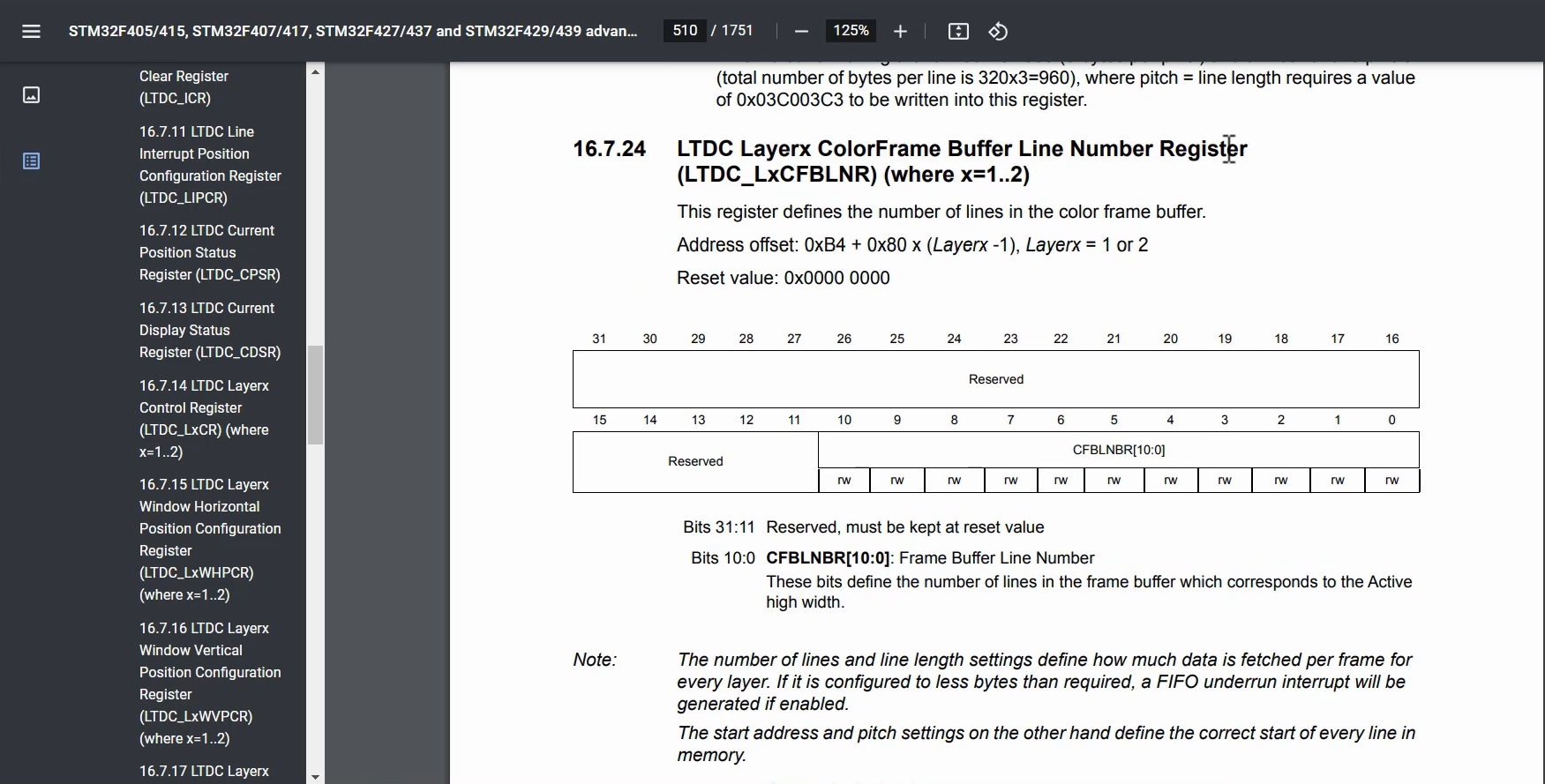
The LTDC Layerx ColorFrame Buffer Line Number Register is responsible for configuring the number of lines in the frame buffer for each layer. It is important to ensure that the configured number matches the actual memory area of the frame buffer. Otherwise, there is a risk of encountering FIFO underrun.
The number of lines and line length settings determine the amount of data fetched per frame for each layer. If the configuration specifies fewer bytes than required, a FIFO underrun interrupt will occur. This means that the LTDC will attempt to fetch more bytes from the frame buffer than it can hold, resulting in a FIFO underrun error.
Therefore, it is crucial to consider these points when configuring the layers of the LTDC.
LTDC Shadow Reload Configuration Register
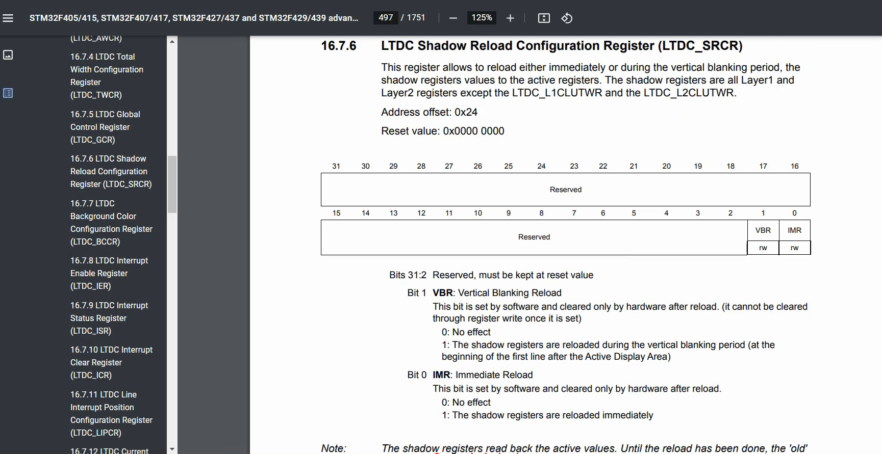
Please note that most of the registers in this layer are Shadow registers. If you set the IMR bit to 1, an immediate reload will occur. This means you need to configure all the LTDC layer registers and, as a final step, set the IMR bit to 1. By doing so, all the values stored in the shadow registers will be loaded into the actual registers. Alternatively, you can automate this process using the VBR field.
If the VBR bit is set to 1, the shadow registers will be reloaded during the vertical blanking period, specifically at the beginning of the first line after the Active Display Area.
FastBit Embedded Brain Academy Courses
Click here: https://fastbitlab.com/course1

