IO pin read exercise implementation
In this article, let’s implement the below exercise.
Exercise:
- Write a program which reads the status of the pin PA0. If the status of PA0 is LOW, then turn off the onboard LED(PD12) and if the status of the PA0 is HIGH, then turn on the LED.
- Change the status of PA0 pin manually by connecting between GND and VDD points of the board.
Code
#include<stdint.h>

int main(void)
{
    uint32_t *const pClkCtrlReg = (uint32_t*)0x40023830;
    uint32_t  *const pPortDModeReg = (uint32_t*)0x40020C00;
    uint32_t  *const pPortDOutReg = (uint32_t*)0x40020C14;
    uint32_t  *const pPortAModeReg = (uint32_t*)0x40020000;
    uint32_t  *const pPortAInReg = (uint32_t*)0x40020010;

//1.enable the clock for GPOID , GPIOA peripherals in the AHB1ENR
    *pClkCtrlReg |= ( 1 << 3);
    *pClkCtrlReg |= ( 1 << 0);

//2.configuring PD12 as output
    *pPortDModeReg &= ~( 3 << 24);
//3.make 24th bit position as 1 (SET)
    *pPortDModeReg |= ( 1 << 24);

//4.Configure PA0 as input mode (GPIOA MODE REGISTER)
    *pPortAModeReg &= ~(3 << 0);

  while(1)
  {
    //5.read the pin status of the pin PA0 (GPIOA INPUT DATA REGISTER)
      uint8_t pinStatus = (uint8_t)(*pPortAInReg & 0x1); //zero out all other bits except bit 0

  if(pinStatus){
    //turn on the LED
    *pPortDOutReg |= ( 1 << 12);
  }else{
    //turn off the LED
    *pPortDOutReg &= ~( 1 << 12);
 }
}
}
1. Enable the clock for GPIOD, GPIOA peripherals in the AHB1ENR.
First, turn on the clock for that. This register will be the same because all these GPIO peripherals are hanging on the AHB1 bus. So, the register will be the same but the bit fields may be different.
Let’s explore what we should do for GPIOD and GPIOA peripherals.
Look at the reference manual of the microcontroller to understand the AHB1ENR register, as shown in Figure 1. The bit position 3 was for GPIOD, the bit position 0 is for GPIOA.
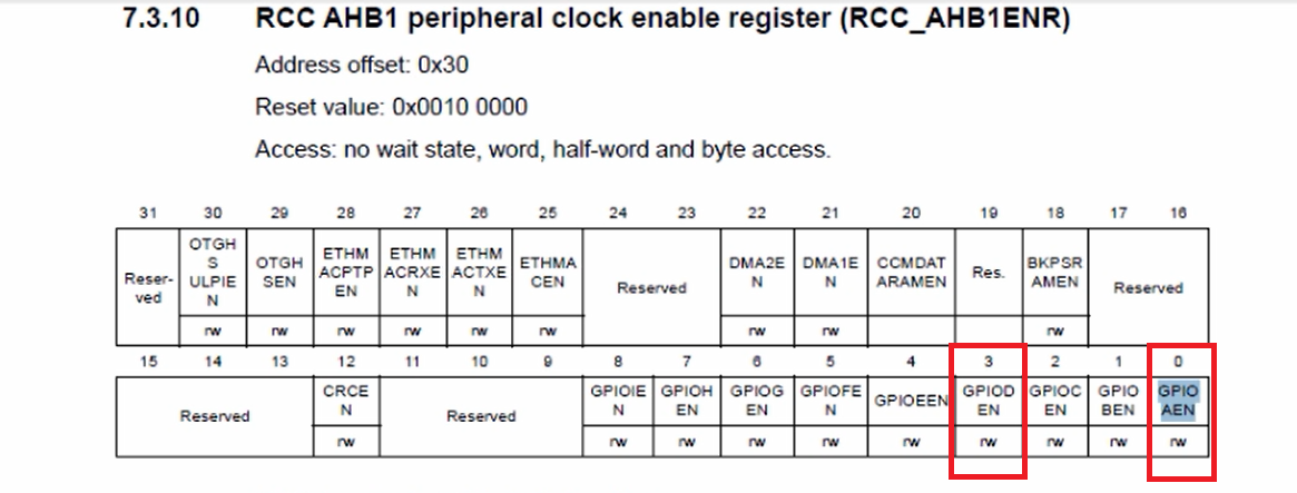
*pClkCtrlReg |= (1 << 3) is for GPIOD and *pClkCtrlReg |= (1 << 0) is for GPIOA.
2. Configure PD12 as output
pPortDModeReg &= ~(3 << 24);
3. Make the 24th bit position as 1(SET)
pPortDModeReg |= (1 << 24);
These codes are for Port D pin number 12. That is for our LED. This code is for configuring PD12 as output.
4. Configure PA0 as input mode (GPIOA MODE REGISTER)
Now, let’s implement the code to configuring PA0 as input.
For this, we have to explore the GPIOA mode register. So, let’s create a variable to store the address of the GPIOA mode register.
Here, 0x40020C00 is an address of the GPIOD mode register. We have to create another pointer to store the address of the GPIOA mode register. That’s why let’s create one variable.
uint32_t *pPortAModeReg = (uint32_t*)0x40020000;
The address of the mode register of GPIO Port A is 0x40020000.
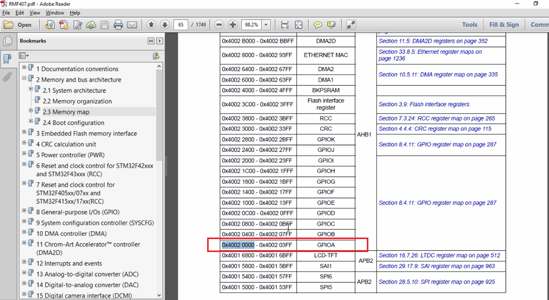
For the GPIO Port A mode register address we have to refer to the reference manual of the microcontroller. Here we have to first go and explore the Memory map to understand the base address of the GPIOA peripheral registers.
Let’s go to the Memory and bus architecture, Memory map, and let’s see where exactly GPIOA is placed, as shown in Figure 2.
What is the offset of the mode register?
The mode register is always at offset 00. So, for every GPIO peripheral, the mode register is at the offset 0 but from different base addresses( Figure 3).
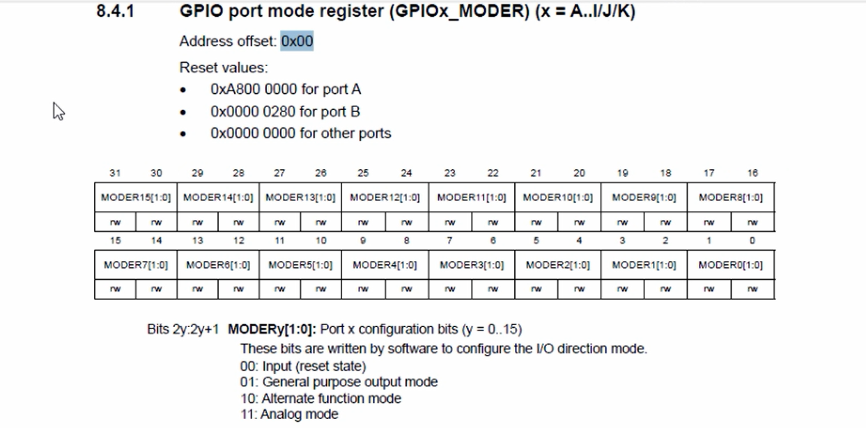
That’s why the offset is 0.
MODER0[1:0] is the place for configuring mode for pin number 0. You have to keep these two bits(0 1) cleared to set the pin mode to input.
Let’s use * pPortAModeReg &= ~(3 << 0);
That clears the first two positions of the Port A mode register.
5. Read the pin status of the pin PA0( GPIOA INPUT DATA REGISTER)
After that, you have to read the pin status of the pin PA0.
For this, you have to refer to the GPIOA INPUT DATA REGISTER.
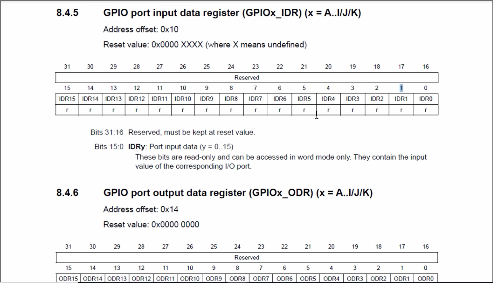
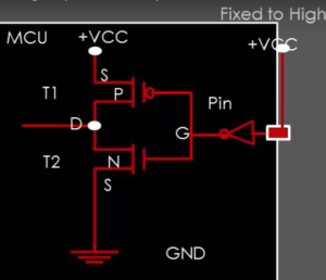
Now let’s explore the input data register. Let’s go to the GPIO section in the reference manual of the microcontroller and in the GPIO section you get the input data register, as shown in Figure 4. You can see that this is a read-only register, you cannot write into this register.
Let’s say Whenever you connect the pin PA0 to high voltage(that is VDD), then the corresponding bit position in this register will be set. In this case, the bit position 0 will be set because we are dealing with pin PA0.
If it is PA1, then bit position 1 will be set if the pin is connected to +VDD. And if you connect the pin to GND, then the corresponding position will be reset.
For that first, we have to find out the address of the Port A input data register.
So, let’s create one more variable GPIOA InReg.
uint32_t *pPortAInReg = (uint32_t*)0x40020010;
The offset is 0x10. That’s why let me put 10 at the end.
After that, create a variable uint8_t pinStatus = (uint8_t)(*pPortAInReg & 0x1)
we have to read this pPortInReg.
When you do this you get 32 bits of data, but what we want is just 1 bit the status of bit position 0. So, we can do masking to 0 out of all other bits except the bit position 0. That’s why we write & 0x1. This will 0 out all the bits except the bit position 0. And after that let me just typecast this to uint8_t.
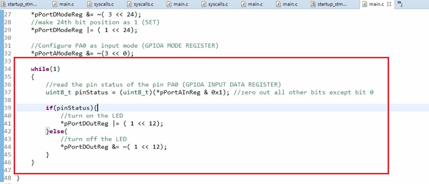
After that, let’s implement decision-making. If pin status is non-zero, then turn on the LED else turn off the LED.
To turn on the LED, we have *pPortDOutReg |= (1 << 12) and to turn off the LED we have this code *pPortDOutReg &= ~( 1 << 12 ).
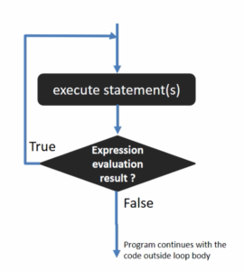
This should work forever. That’s why let’s keep while(1) in a super loop.
This should happen again and again, you have to read the pin status and take the decision. This should happen forever. So, let’s implement the infinite while loop.
FastBit Embedded Brain Academy Courses
Click here: https://fastbitlab.com/course1