Embedded target
In this article, we focus on the STM32F407VGT6 microcontroller-based DISCOVERY Board, serving as our embedded target.
The STM32F407VGT6 board is based on the STM32F407 microcontroller, which is a part of STMicroelectronics’ STM32F4 series. This microcontroller is built on the ARM Cortex-M4 architecture and offers a variety of features suitable for a wide range of applications, from embedded systems to industrial control and more.
The STM32F407VGT6 board is a development platform that helps engineers and developers prototype and develop applications using this microcontroller.
Some of the important features of STM32F407VGT6 board:
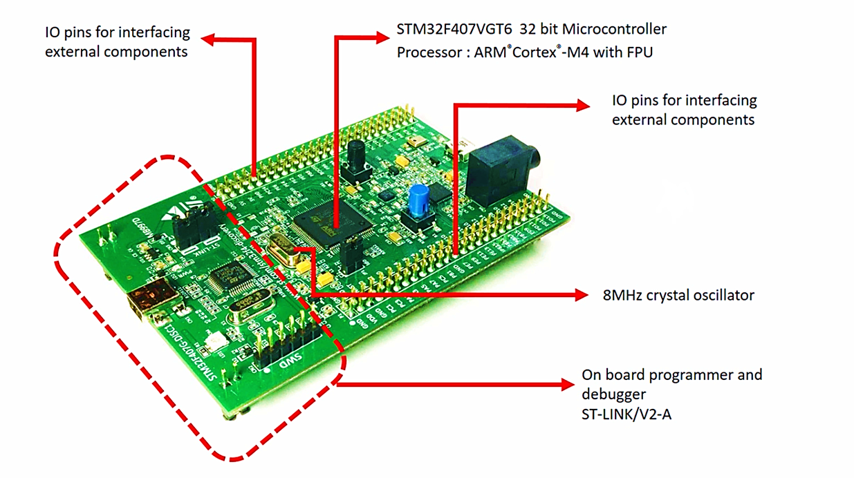
- Microcontroller Core: Central to the board’s functionality is the STM32F407VGT6 microcontroller, a 32-bit ARM Cortex-M4 processor with a floating-point unit (FPU). This microcontroller runs at clock speeds of up to 168 MHz.
- Rich IO Pin Set: The board provides numerous GPIO pins to connect external components such as LEDs, buttons, LCDs, and keypads, facilitating versatile interfacing.
- Clock Oscillator: An onboard 8MHz crystal oscillator supplies the necessary clock signal to the microcontroller.
- Integrated Programmer and Debugger: The board features its own programmer and debugger, the ST-LINK/V2-A, eliminating the need for external hardware. This simplifies programming and debugging processes.
- Memory:
- Flash Memory: The STM32F407VGT6 offers up to 1 MB of Flash memory for program storage.
- RAM: It possesses up to 192 KB of SRAM for data storage.
- Peripherals:
- General-Purpose I/O (GPIO): The board includes multiple GPIO pins for external device interfacing.
- Serial Interfaces: UART, SPI, and I2C interfaces enable communication with other devices.
- USB: The board supports both USB Full-Speed and High-Speed interfaces for various applications.
- ADC and DAC: Analog-to-Digital and Digital-to-Analog Converter interfaces enable analog signal conversion.
- PWM: Pulse Width Modulation outputs facilitate applications like motor control and LED dimming.
- Timers: Multiple timers are available for delay generation, PWM signal production, and more.
- Connectivity:
- Ethernet: Some versions of the board feature an Ethernet interface for networking.
- CAN: Controller Area Network interface enables communication in automotive and industrial contexts.
- SD Card Slot: Certain variants may include an SD card slot for external memory storage.
- Display: Certain iterations of the board offer a display interface, allowing connection to different types of displays such as TFT LCDs.
- Debugging and Programming:
- Debugging: The board incorporates debugging interfaces like SWD (Serial Wire Debug) for programming and debugging purposes.
- Bootloader: The microcontroller often features a built-in bootloader for easy programming via USB or other interfaces.
- Power Supply: The board requires a 3.3V power supply, potentially with voltage regulators for generating necessary voltage levels.
- Expansion: The board may feature headers and connectors for effortless attachment of additional modules or expansion boards.
- Programming and Development: The board is typically programmable through various development environments such as STM32CubeIDE or compatible tools.
So, when you install the STM32CubeIDE, the driver for this programmer and debugger will be installed automatically on your machine. Otherwise, ST also gives the separate device drivers for this ST-LINK hardware, so you can also download it from the ST’s website and install it.
For detailed information about the board please refer to the user manual and schematic given by the ST.
Go to the below link, and you can download those documents.
https://www.st.com/en/evaluation-tools/stm32f4discovery.html
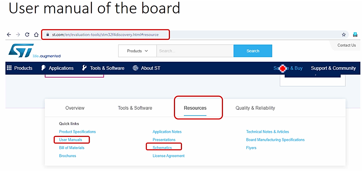
When you go to that link, you will find a section called Resources. Just click over that, and then it will display all the related documents, such as user manuals and schematics.
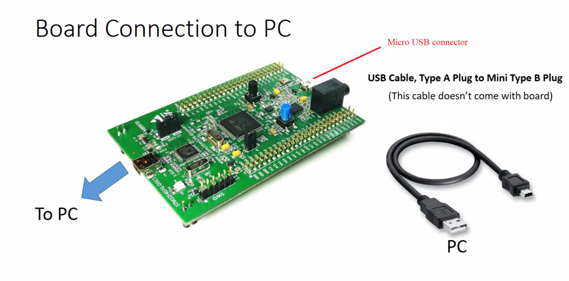
How do you connect this board to the PC?
To connect the board to a PC, a mini USB cable is required (not included with the board). Connect the mini USB connector on the board to the PC using the cable.
This board also has a micro USB connector, so don’t use that. That’s the only connection you have to do to start using this board. That’s about the target.
FastBit Embedded Brain Academy Courses
Click here: https://fastbitlab.com/course1

