Code and Data of the program using memory browser
In this article, let’s learn the code and Data of the program using a memory browser.
Here we have a program. The project name is 003Add. And it is a very simple program, and here we have three global variables. Two global variables are initialized to some data. And after that, I’m just adding those to global variables, and I store the result into another global variable. Look at the below program; we have data. After that, on the data, we are doing an arithmetic operation, and after that, we are storing the result back into the variable.
#include <stdio.h>

/* global variables */
int g_data1 = -4000;
int g_data2 = 200;
int result = 0;

int main(void)
{
   result = g_data1 + g_data2;
   printf("Result = %d\n",result);
   for(;;);
}
Let’s compile and let’s download this code into the microcontroller. And after that, let’s analyze where exactly the data are stored and where exactly the program instructions are stored. First, compile this code.
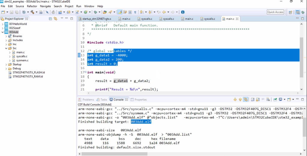
In Figure 1, you can see that we got the executable, that is .elf. This is the file that we are going to download into our target. And please note that this data is also part of this 003Add.elf executable. So, this data is hidden inside this 003Add.elf.
First, let’s load this 003Add.elf into the target. Right-click on the project, click on Debug As and click on STM32 MCU C/C++ application.
The code is downloaded into the target, and the eclipse went into the debug perspective.
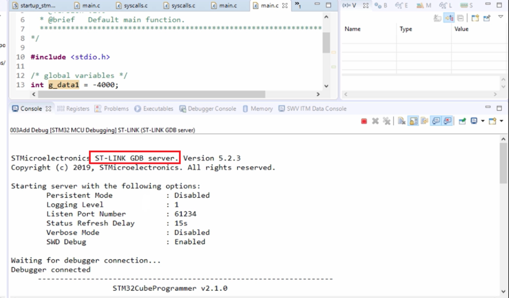
Here you can see the log(Figure 2), the ST-LINK GDB server communicating with the ST-LINK circuitry of the board.
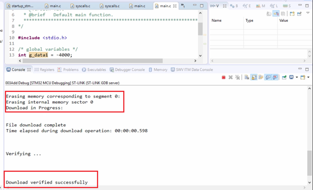
After that, here you can see that(Figure 3) it erased the internal memory that is embedded flash. And after that downloaded the code.
Download and verified successfully→ That means the executable part of the .elf file is downloaded into the non-volatile memory of the microcontroller, which is nothing but flash.
Now, let’s examine the flash contents to see whether the instructions are really stored there or not because that is our program memory. So, we’ll first examine the program memory of the microcontroller by using our debugger.
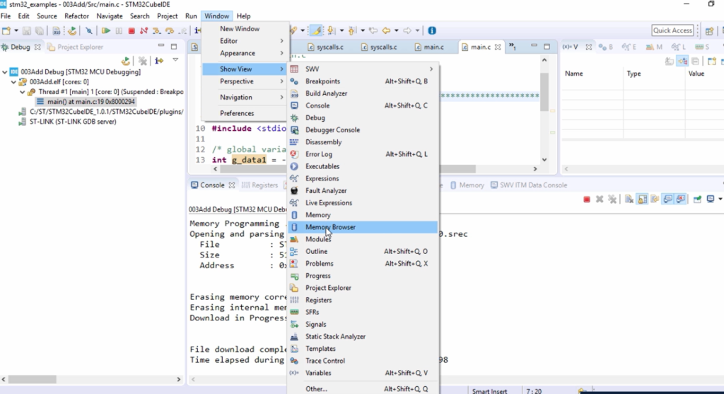
To examine the program memory, you have to look into the memory window. So, to get the memory window, go to Window, go to Show View, and here you can see memory and memory browser. Now let’s open the Memory browser.
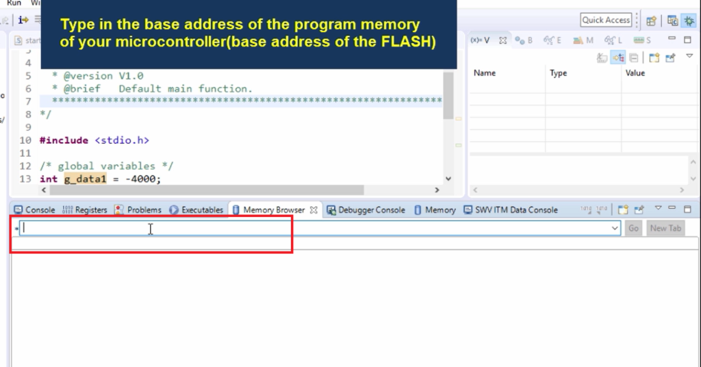
Here, you have to type the base address of the program memory of your microcontroller.
What is the base address of the program memory of our microcontroller?
These details you have to get from the reference manual of the microcontroller.
Let’s open the reference manual of our microcontroller to see the address. Here I’m using is STM32F407 microcontroller. Open the reference manual of your microcontroller, and go to the Embedded flash memory section. Let’s go there. You have to browse through this section, and it shows the flash module organization table(as shown in Figure 6).
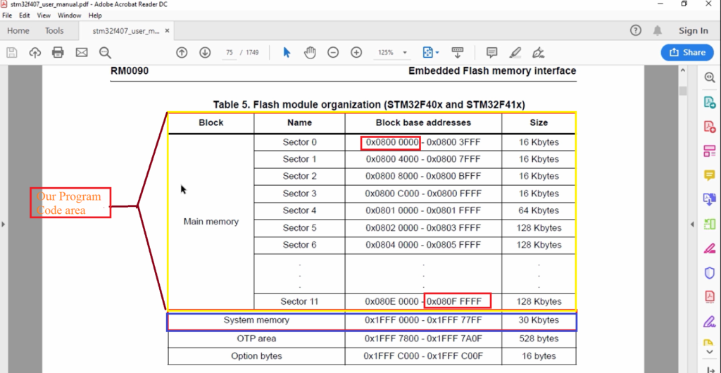
If you’re using STM32 based microcontrollers, you should see a similar table, but addresses may be different or maybe the same. The number of sections is maybe different. But suppose you are using some other microcontrollers from an entirely different vendor like Texas Instruments, NXP, or something like that. In that case, you should be able to get the base address of your program memory.
Here you can see the embedded non-volatile memory organization, which is the main memory. This is actually a flash memory. This is a flash memory of 512 Kilobytes.
And apart from that, that is a read-only memory. That’s what we call as System memory. The user cannot write into this read-only memory. So, the ST has already placed a bootloader code into this memory.
In this table, in our program code area, the base address is 0x0800 0000, and the final address is 0x080F FFFF. From here to here, we can save our program instructions. When you download the code, the code will start accumulating right from the 0x0800 0000 address onwards.
Now let’s examine this memory address, and let’s see whether the codes are really present from this location onwards or not.
Copy 0x0800 0000 base address, go to the IDE and paste in the memory browser, and hit enter.
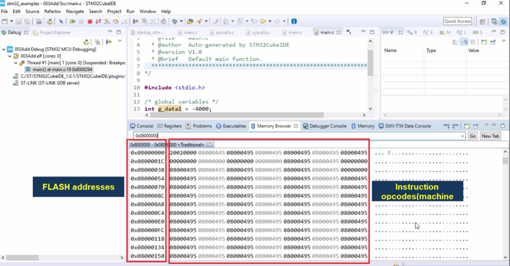
Look at Figure 7. The memory window displays the contents of memories from 0x08000000 this memory location onwards. And this memory location happens to be the memory location of the flash memory in our microcontroller.
Here it shows the program instructions or machine codes are stored. All these are machine codes. If you want to check this memory contents byte by byte, you can do that. Here it shows you word by word, which means 32 bits by 32 bits.
For example, 20020000 is the contents of this location which is 0x8000000.
If you want to check byte by byte, you have to do some settings here. Right-click on this window, and you get columns. So, set the columns to 1.
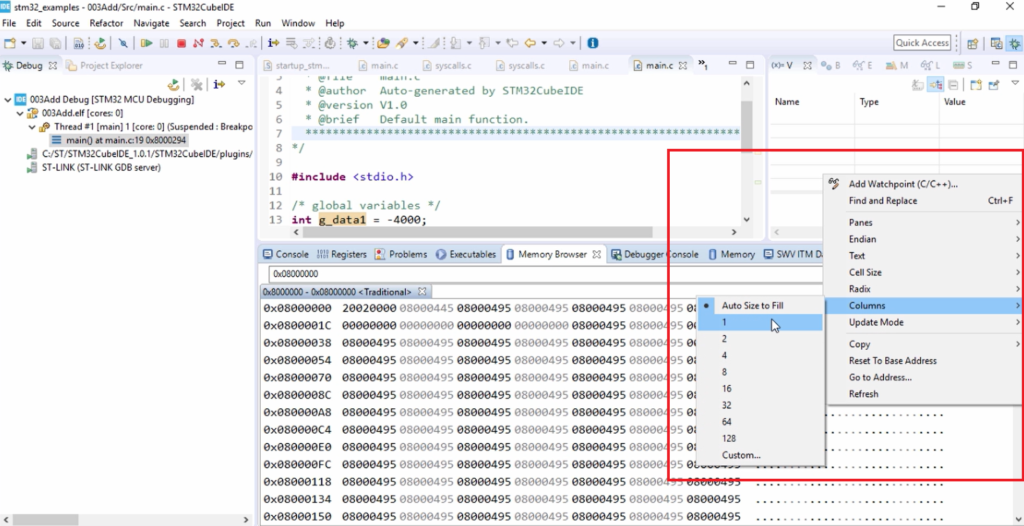
Now you can see it word by word.
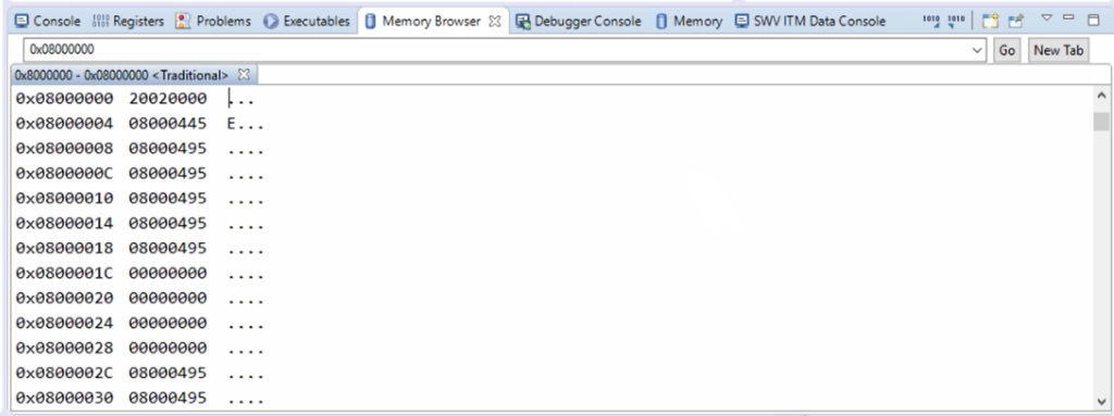
If you want to see byte by byte, then again select, go to cell size, and click on 1 byte.
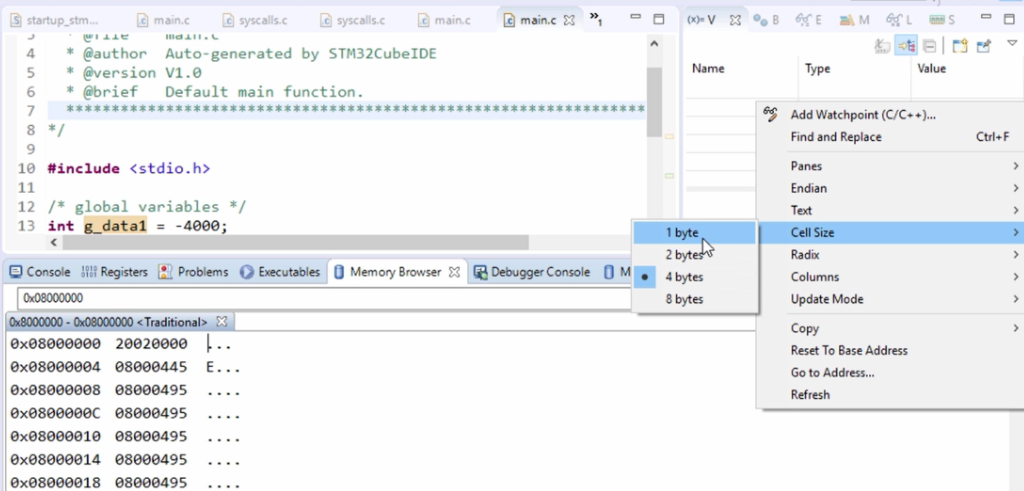
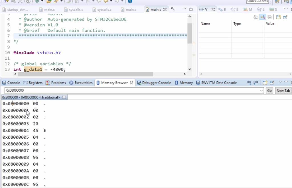
So, here it is(Figure 11). At the memory location is 0x08000000, the content is 00; at the memory location is 0x08000001, the content is 00, like that. That’s about the program memory.
Let’s examine the data memory. The data memory is SRAM. So, before checking the SRAM contents, we have first to find out the base address of the SRAM memory, that is, the data memory in our microcontroller.
For that, again, we have to refer to the reference manual. The reference manual should mention the base address of the SRAM. That is there in section 2.3.1. Embedded SRAM.
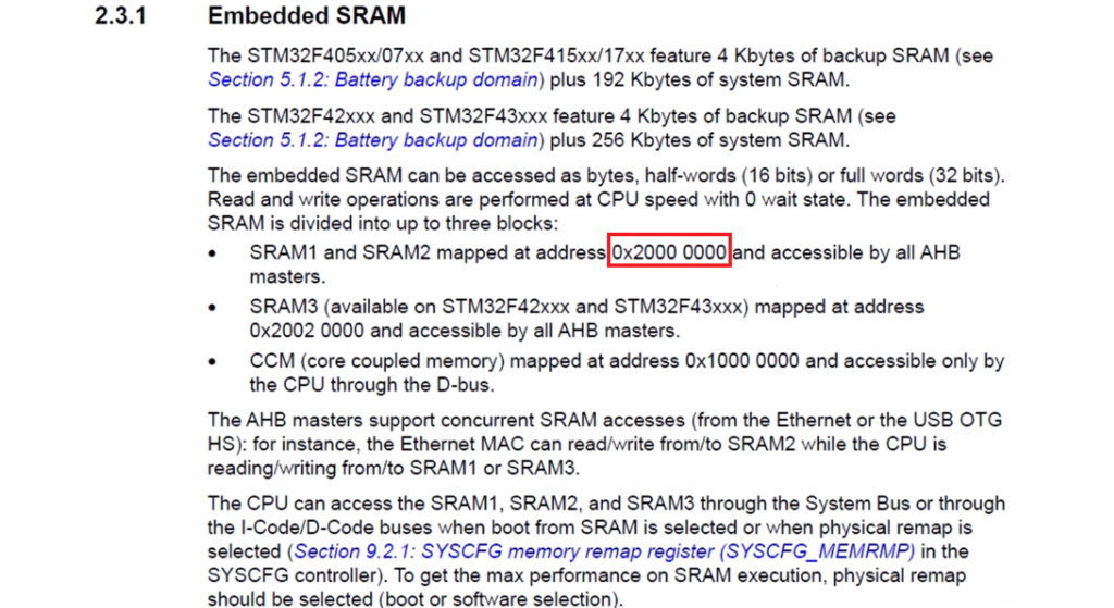
Here we can see that( Figure 12) SRAM1 and SRAM2 mapped at address 0x20000000. That means, in the memory map of the microcontroller, this address(0x20000000) belongs to SRAM1, which means from this location onwards SRAM starts. That is, SRAM1 starts for this microcontroller. So, many microcontrollers have only one SRAM. All these are marketing techniques of the microcontroller. Since it is a high-end microcontroller, it has multiple SRAMs, which are used for different purposes. But the primary data memory is SRAM1, and its address starts from the 0x20000000 memory location. Copy this address, go to our memory browser and paste this address, and hit enter.
This is data memory, and the data that is -4000 is actually stored here, as shown in Figure 13.
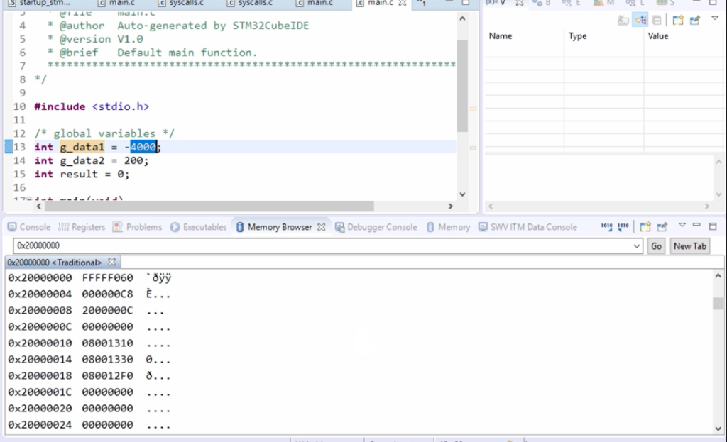
I can show that by changing the radix to Hex or a Decimal signed. Here I change the format to decimal signed, as shown in Figure 14.
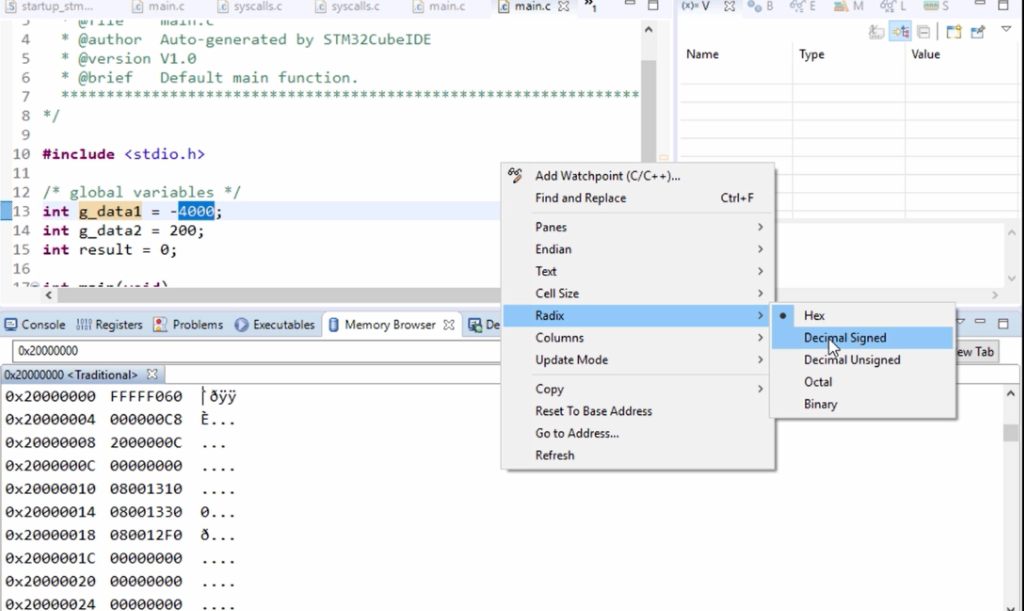
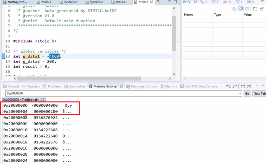
You can see that 0x20000000 at this location -4000 is stored. And 0x20000004 at this location 200 is stored.
FastBit Embedded Brain Academy Courses
Click here: https://fastbitlab.com/course1

