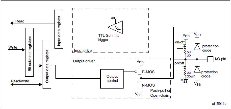
Output configuration of GPIO Pin in Push pull mode
In this article, let’s understand the GPIO output mode.
For output mode, there are two configurations.
- open drain,
- push-pull.
In this article, let’s see about push-pull output type configuration.
In push-pull mode “0” in the Output data register activates the N-MOS whereas a “1” in the Output data register activates the P-MOS. The data present on the I/O pin is sampled into the input data register over every AHB1 clock cycle. Read access to the input data register gets the I/O state. Read access to the output data register gets the last written value.
To set GPIO output type register in push-pull mode, in GPIO_OTYPER register bit is set to “0”.
In the following article, let’s see Output configuration of GPIO Pin in Open drain mode.
FastBit Embedded Brain Academy Courses,
Click here: https://fastbitlab.com/course1