SPI bus configuration discussion: Full duplex, Half-duplex, and Simplex
In this article, let’s explore customizing SPI bus in various bus configurations. The SPI allows the microcontroller to communicate using different settings, depending on the device targeted and application requirements.
SPI bus configuration: Full duplex
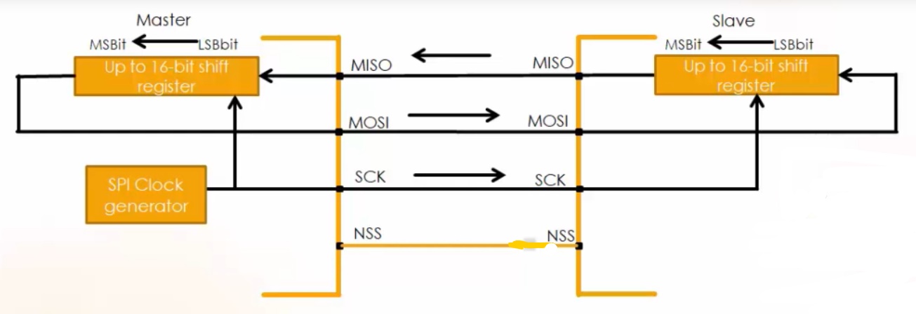
From Figure 1. Full duplex data communication occurs during each clock cycle. The master shift register transmits the data to the slave on the MOSI line, and the slave receives it. At the same time, the slave shift register sends the data to the master on the MISO line, and the master gets it. Transmission may continue for any number of clock cycles. When complete, master idles the clock and releases the SS line.
So, in full-duplex communication shift registers of both master and slave are linked using two unidirectional lines between MOSI and MISO pins. By default, SPI configures for full-duplex communication.
SPI bus configuration: Half-duplex
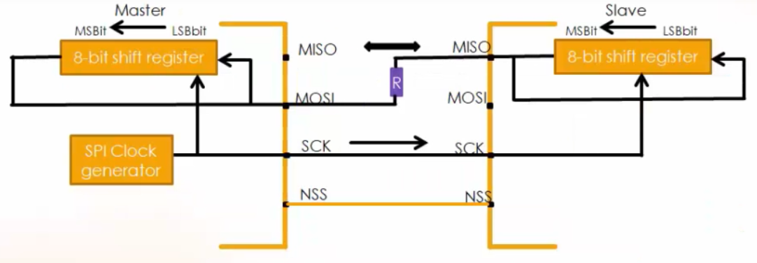
From Figure 2. The SPI can communicate in half-duplex mode by setting the BIDIMODE bit in the SPIx_CR1 register.
In half-duplex data communication, one single cross-connection line is used to link the shift registers.
In this data communication, there is only one data line. The MOSI of the master connects to the MISO of the slave. And there must be one resistor in between a typical value may be 1kiloohm. So, the transfer happens in the direction selected reciprocally by both the master and the slave. That means, the slave transmits data on the MISO line, and the master receives it. The MOSI line of the slave remains inactive. Or the master sends the data on the MOSI line, and the slave gets it. The MISO line of the master remains inactive.
SPI bus configuration: Simplex

The SPI can communicate in simplex mode by setting the SPI in transmit-only or receive-only using the RX ONLY bit in the SPIx_CR2 register. Simplex, as its name indicates the communication is in simple mode.
There are two types of communication in simplex mode, one is transmitting only, and the other one is receiving only.
From Figure 3. The master is in transmit mode, and the slave is in receive mode. The MOSI of the master connects to the MOSI of the slave. And both the MISO lines are disconnected.
In all of the above communications, the NSS pin is optional because only one slave considered.
FastBit Embedded Brain Academy Courses
Click here: https://fastbitlab.com/course1

